High-efficiency inverter topology

An inverter, high-efficiency technology, applied in the field of power conversion, can solve the problems of less transformerless inverter, high switching loss, low conversion efficiency, etc., to reduce switching voltage and rated voltage requirements, reduce switching loss, low cost effect

Inactive Publication Date: 2013-09-18
FONRICH NEW ENERGY TECH LTD
View PDF8 Cites 12 Cited by
  • Summary
  • Abstract
  • Description
  • Claims
  • Application Information

AI Technical Summary

Problems solved by technology

However, the inverter topology without a transformer is prone to high-frequency common-mode leakage current between the two sides because there is no isolation between the input and output sides.
Few existing topologies are suitable for transformerless inverters, and each has its own disadvantages
For example, the traditional H-bridge inverter topology has bipolar modulation and unipolar modulation; if bipolar modulation is used, although there is no high-frequency common-mode leakage current problem, its switching loss is high and conversion efficiency is low; If there is a common-mode leakage current problem when using unipolar modulation

Method used


Image

  • High-efficiency inverter topology
  • High-efficiency inverter topology
  • High-efficiency inverter topology

Examples


Embodiment Construction

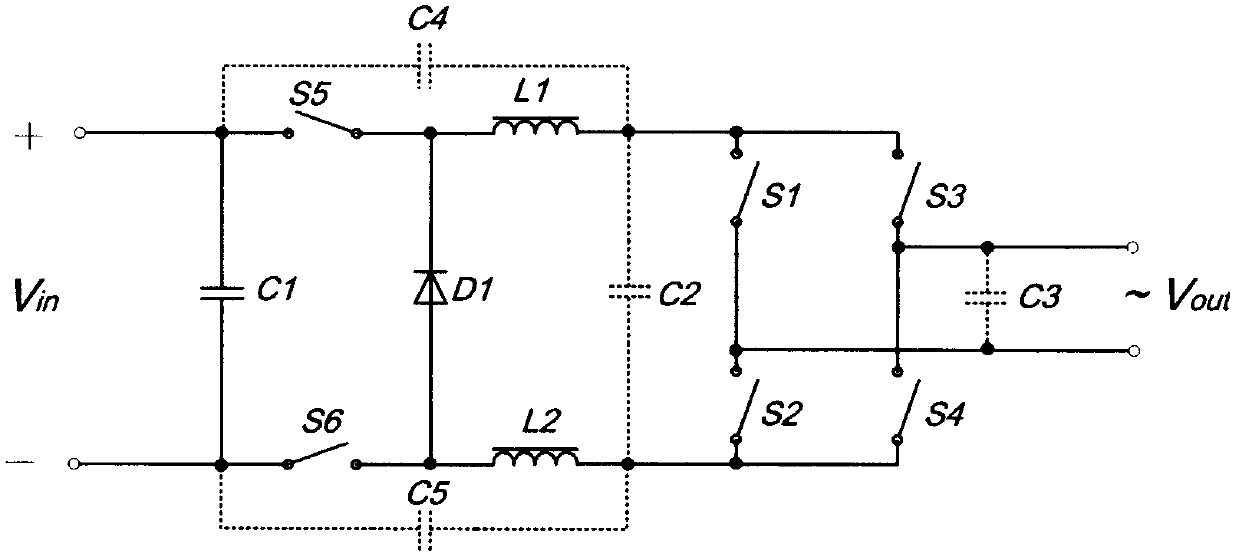
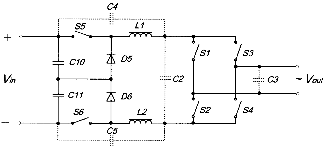
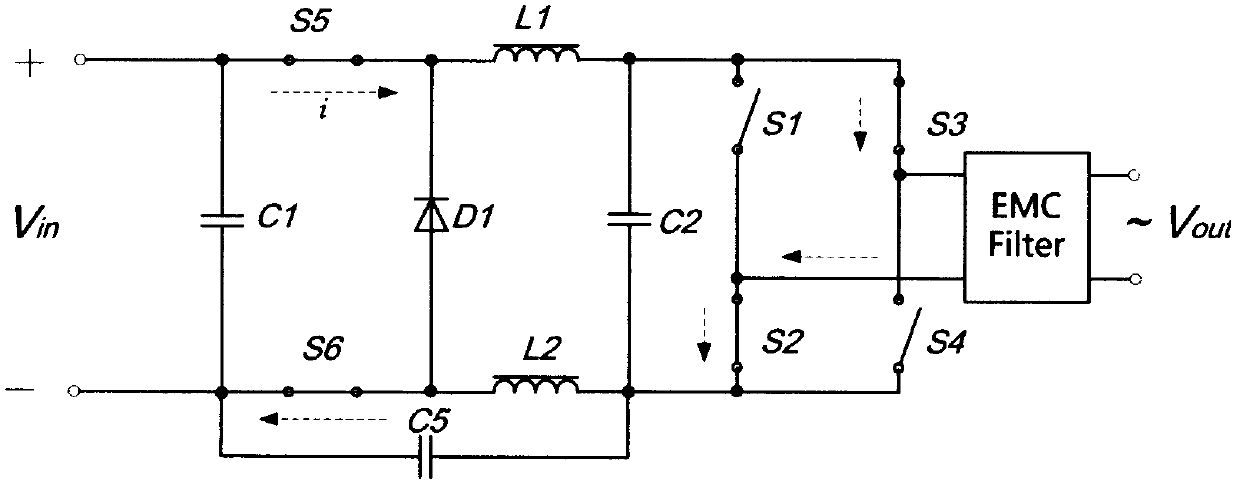
[0018] image 3 , Figure 4 , Figure 5 , Image 6 It is the switching state of the inverter example implemented using the inverter topology of the present invention during operation. image 3 with Figure 4 Is when the inverter outputs a positive half wave of AC, Figure 5 with Image 6 This is when the inverter outputs a negative half wave of AC. When the inverter outputs a positive AC half-wave, the commutation switches S2 and S3 are kept in the on state; the commutation switches S1 and S4 are kept in the off state, and their blocking voltage is Vout. When the inverter outputs a negative half-wave of AC, the reversing switches S1 and S4 remain in the on state; the reversing switches S2 and S3 are kept in the off state, and their blocking voltage is Vout. Chopper switches S5 and S6 are switched at high frequency at the same time, image 3 with Figure 5 Is the situation when they are opened, Figure 4 with Image 6 This is the situation when they are off. When S5 and S6 ar...


PUM


Abstract

The invention discloses a high-efficiency inverter topology which inverts direct current into alternating current in a lower cost and high efficiency manner, simultaneously does not cause a common mode interference problem, and can be conveniently applied to inverter systems without isolation transformers. The principle of the topology is that high-frequency chopping switches are respectively arranged on a positive end and a negative end of a direct current input side and switched on/off simultaneously, and the duty ratios of the switches are regulated so as to vary the amplitudes of the output voltage; flat wave inductors are respectively connected at the rear stages of the switches, and a subsequent flow circuit is arranged at one sides, which are connected with the chopping switches, of the two flat wave inductors, so that the subsequent current of the flat wave inductors are ensured when the chopping switches are switched off; H inverting bridges are arranged at the rear stages of the inductors and invert at the output frequency which is required by an inverter, and accordingly, inverting is realized. By utilizing the topology, the switching voltages of switching tubes are reduced, and accordingly, the switching loss of a system is decreased; and moreover, the topology does not cause the common mode interference problem and can be used for the inverter systems without the isolation transformers.

Description

Technical field [0001] The invention belongs to the field of power conversion. It is a topological structure that converts direct current into alternating current. It can be widely used in inverters that require high conversion efficiency or common mode current suppression, such as photovoltaic inverters and wind power inverters. Changer and so on. Background technique [0002] With the development of industry, the requirements for inverter conversion efficiency are getting higher and higher, especially in industries such as new energy power generation, smart grid, and flexible AC and DC transmission. Increasing the conversion efficiency of the inverter can save more electric energy and also reduce the heat dissipation requirements of the inverter itself. The decisive factor of inverter efficiency is the topology of the inverter. The quality of the topology determines the efficiency and cost of the inverter. Inverters in many applications, such as photovoltaic grid-connected in...

Claims


Application Information

Patent Timeline
Patent Type & Authority Applications(China)
IPC IPC(8): H02M7/48
Inventor 张永
Owner FONRICH NEW ENERGY TECH LTD
Why Eureka
Try Eureka