Flotation apparatus and flotation process

A flotation machine and flotation technology are applied in the field of flotation machines, which can solve the problems of uneconomical flotation process and achieve high-yield effects.

Active Publication Date: 2013-09-18
PRIMETALS TECH GERMANY
View PDF9 Cites 4 Cited by
  • Summary
  • Abstract
  • Description
  • Claims
  • Application Information

AI Technical Summary

Problems solved by technology

However, if agitators are used, this can be achieved with a very high energy input

Method used


Image

  • Flotation apparatus and flotation process
  • Flotation apparatus and flotation process
  • Flotation apparatus and flotation process

Examples


Embodiment Construction

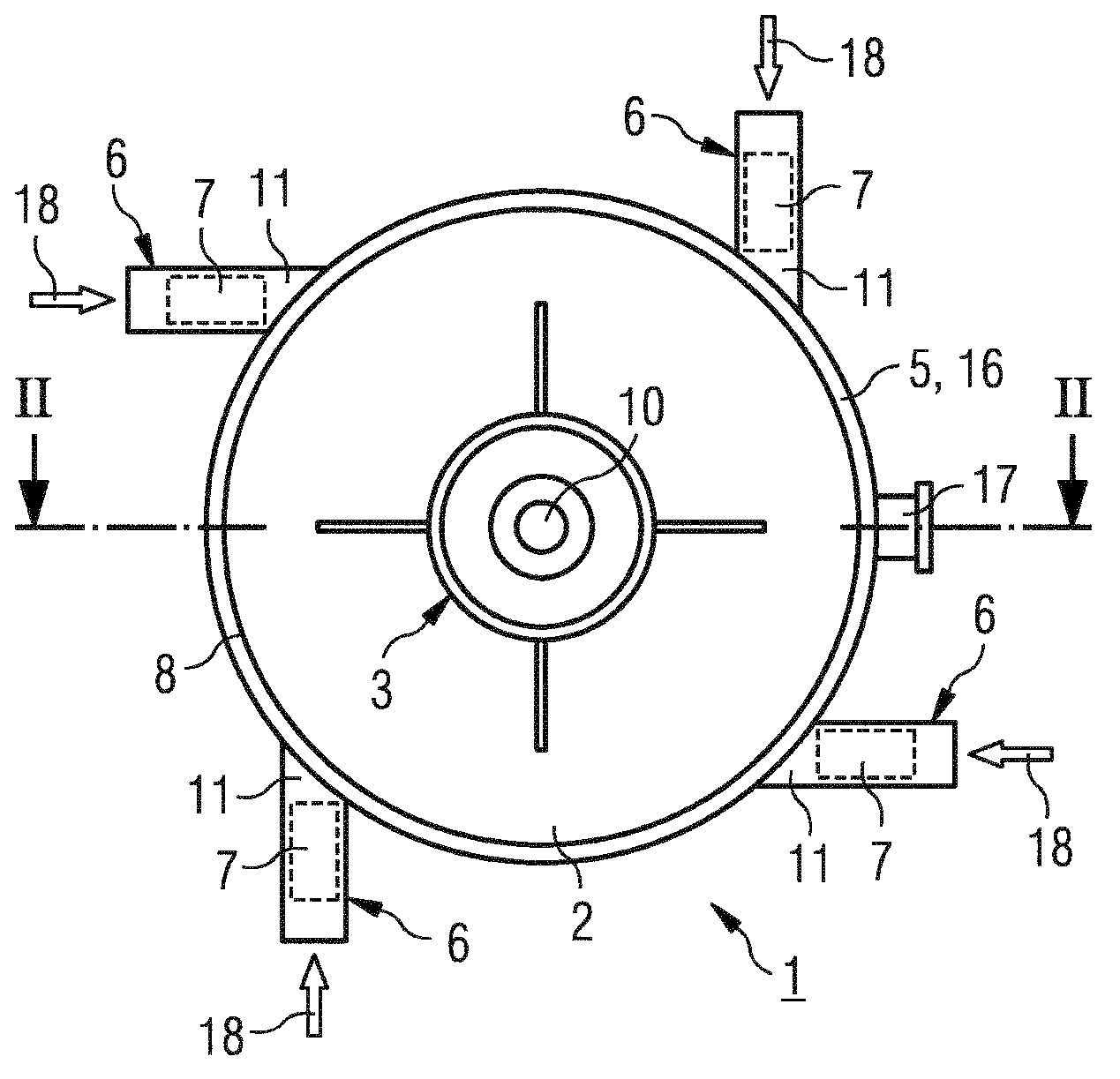
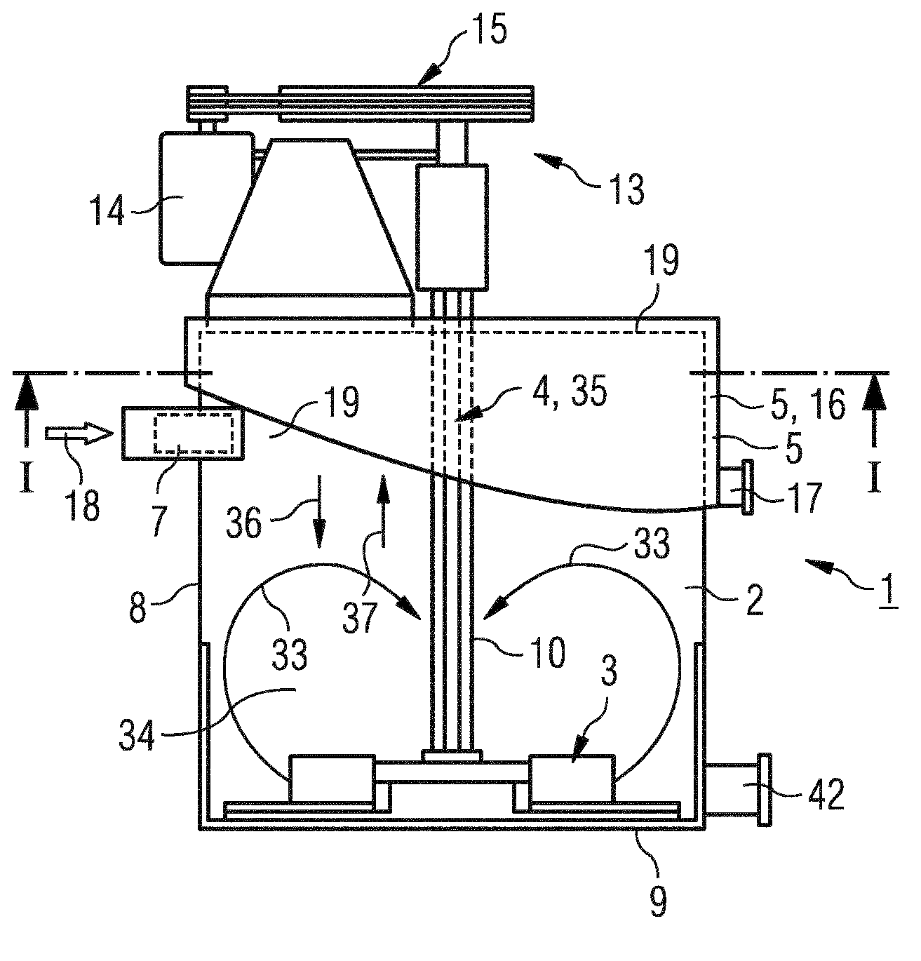
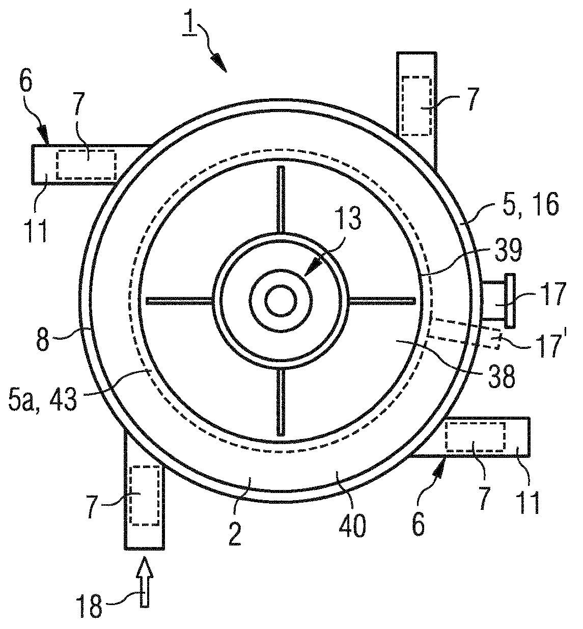
[0017] in accordance with Figure 1-6 The flotation machine 1 shown in the schematic diagram comprises a flotation chamber 2, a froth collecting device 5 and four charging pipes 6 arranged at intervals from each other in the circumferential direction on the flotation chamber 2, and these charging pipes respectively include injectors 7 form of the first mixing device M1, or in which the injector is integrated. Arranged in the flotation chamber 2 is a further second mixing device M2 comprising a stirrer 3 and an aeration device 4 associated with the stirrer 3 . The flotation chamber 2 is delimited by side walls 8 and a bottom 9 having an annular cross-sectional shape. An electric stirrer 3 , designed for example as a stator-rotor system, is arranged on the bottom 9 of the flotation chamber 2 , or in the region below it. The stirrer is connected via a hollow shaft 10 to a drive unit 13 which includes, for example, an electric motor 14 and a transmission 15 connecting the electr...


PUM


Abstract

The invention relates to a flotation apparatus with a flotation chamber (2) having a side wall and a base (9), a stirrer (3), a sparging device (3) associated with the stirrer, a first foam-collecting device (5) arranged in an upper region of the flotation chamber for a foam product formed in the course of flotation, and a charge line (6) for charging the flotation chamber with slurry, wherein the charge line opens into the flotation chamber at a point (19) above the stirrer and an ejector (7)is present in the charge line. The invention also relates to a flotation process which is performed in two stages within a flotation chamber (2) of a flotation apparatus (1), wherein an ejector (7) is used in a first flotation stage and a stirrer (3) in a second flotation stage.

Description

technical field [0001] The invention relates to a flotation machine with a stirrer as dispersing device and to a flotation method. For example, the known flotation machine from the patent document DE1279573 comprises a flotation chamber delimited by side walls and a bottom, a slurry inlet pipe, an agitator, an aeration device assigned to the agitator and a device arranged on the upper region of the flotation chamber. And a froth collection device for collecting froth products formed during flotation. Background technique [0002] Flotation is a physical separation method used to separate mixtures of particles based on their differing surface hydrophilicity. In this method, for example for separating minerals and gangues, a gas, for example air or nitrogen, is introduced into the particle mixture in the form of an aqueous suspension, ie a slurry, by means of ventilation. In addition, flotation chemicals are added to the slurry to hydrophobicize the surface of the effective ...

Claims


Application Information

Patent Timeline
IPC IPC(8): B03D1/20B03D1/24B03D1/22B03D1/14
CPCB03D1/1406B03D1/22B03D1/24B03D1/247B03D1/1475B03D1/1456B03D1/1493B03D1/16B03D1/1418B03D1/02B03D1/20
Inventor 利拉·格罗斯曼沃尔夫冈·克里格尔施泰因
Owner PRIMETALS TECH GERMANY
Why Eureka
Try Eureka