Flower catheter for mapping and ablating veinous and other tubular locations

一种导管、管状结构的技术,应用在导管、应用、诊断记录/测量等方向,能够解决增加消融过程持续时间、复杂性和/或成本等问题

Inactive Publication Date: 2013-09-25
BIOSENSE WEBSTER (ISRAEL) LTD
View PDF20 Cites 33 Cited by
  • Summary
  • Abstract
  • Description
  • Claims
  • Application Information

AI Technical Summary

Problems solved by technology

Therefore, testing the isolated wire to complete requires repositioning the catheter or using a second catheter, both of which increase the duration, complexity and / or cost of the ablation procedure

Method used


Image

  • Flower catheter for mapping and ablating veinous and other tubular locations
  • Flower catheter for mapping and ablating veinous and other tubular locations
  • Flower catheter for mapping and ablating veinous and other tubular locations

Examples


Embodiment Construction

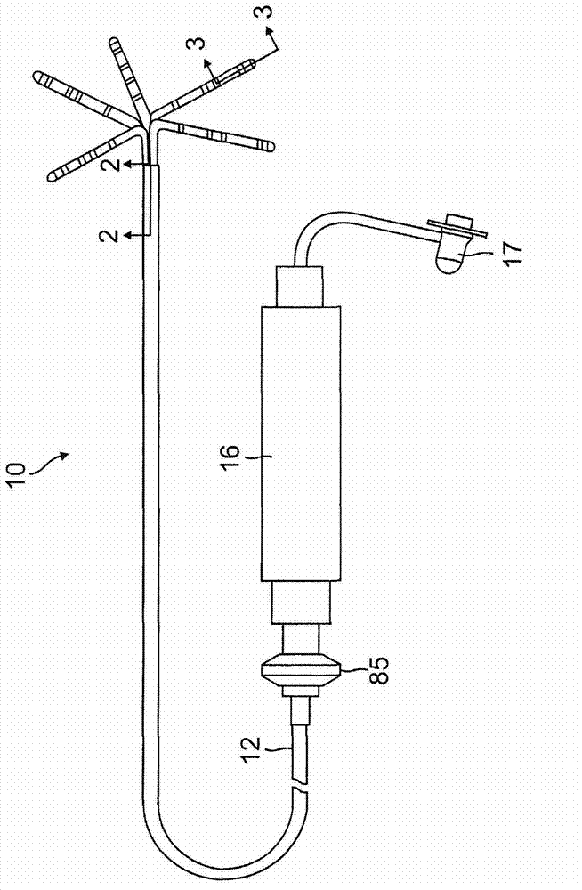
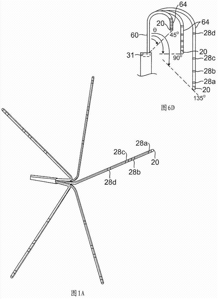
[0035] The present invention involves such as figure 1 Catheter 10 is shown having a distal assembly 18 comprising a plurality of spines 14 . Each spine carries at least one electrode, preferably a tip electrode 20 and at least one ring electrode 28, so that when the spine is positioned in contact with the tissue of the tubular structure at or near the heart, each spine is able to obtain an electrical signal and act on the tissue. ablation. Such as figure 1 As shown, catheter 10 includes: an elongated catheter body 12 having a proximal end and a distal end; a control handle 16 at the proximal end of catheter body 12; and a distal assembly 18 including a plurality of spines 14 which The spine is mounted at the distal end of the catheter body 12 .

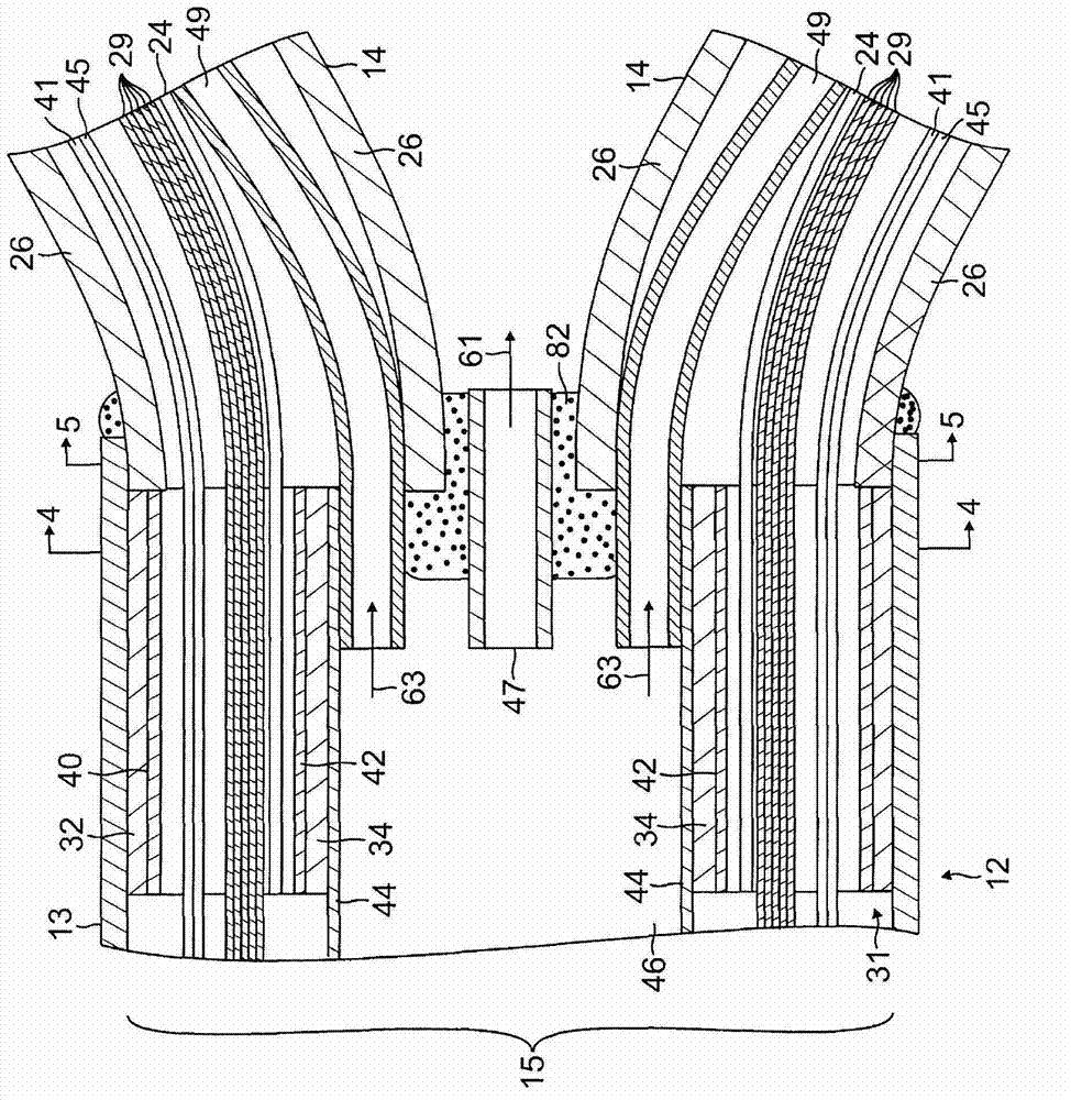
[0036] Such as figure 1 with 2 As shown, the catheter body 12 comprises an elongated tubular construction having a single axial or central lumen 15, but may optionally have multiple lumens along all or part of its length if desi...


PUM


Abstract

An improved catheter particularly useful for tubular regions at or near the heart has a distal assembly having at least two spines, each having a proximal end fixed to the catheter and a free distal end. Each spine has a support arm supporting the spine in a generally L-shaped configuration when the spine is in a relaxed, neutral state and in a generally U-shaped configuration when the spine is inserted into a tubular region. The spine has a proximal portion and a distal portion that may be straight or curved or zig-zagged. Each spine carries a tip electrode and at least one ring electrode that come into contact simultaneously with heart tissue for ablation and / or sensing electrical activity along two different circumferences of the tubular region simultaneously.

Description

Background technique [0001] Leads have been commonly used in medical practice for many years. They are used to stimulate and map electrical activity in the heart, and to ablate sites of abnormal electrical activity. In use, the lead is inserted into a ventricle. Once the catheter is located, the location of the abnormal electrical activity within the heart is located. [0002] One localization technique involves the electrophysiological mapping process whereby electrical signals emanating from conductive intracardiac tissue are systematically monitored and these signals form a map. By analyzing the map, a physician can identify interfering electrical pathways. A conventional method for mapping electrical signals from conductive cardiac tissue is the percutaneous introduction of an electrophysiology catheter (lead lead) with mapping electrodes mounted on the distal tip of the electrophysiology catheter. The catheter is manipulated so that the electrodes are in contact with ...

Claims


Application Information

Patent Timeline
Patent Type & Authority Applications(China)
IPC IPC(8): A61B18/12A61B5/361A61B5/296
CPCA61B2017/00867A61B2018/1467A61B2218/002A61B2018/00357A61B2018/00577A61B2018/00839A61B18/1492A61B5/4848A61B5/6859A61B2018/0016A61B5/287A61B18/12A61B5/283A61B5/25
Inventor I.方
Owner BIOSENSE WEBSTER (ISRAEL) LTD
Why Eureka
Try Eureka