
Universal auxiliary welding device for microwave antennas
A technology for auxiliary devices and microwave antennas, applied in auxiliary devices, welding/cutting auxiliary equipment, welding equipment, etc., can solve the problems of poor versatility and inability to fix microwave antennas, and achieve good heat dissipation, not easy to deform, and easy to adjust Effect
Patent Information
- Authority / Receiving Office
- CN · China
- Patent Type
- Applications(China)
- Current Assignee / Owner
- Publication Date
- 2013-09-25
Smart Images
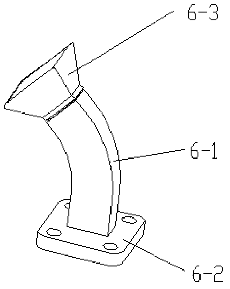
Figure 1 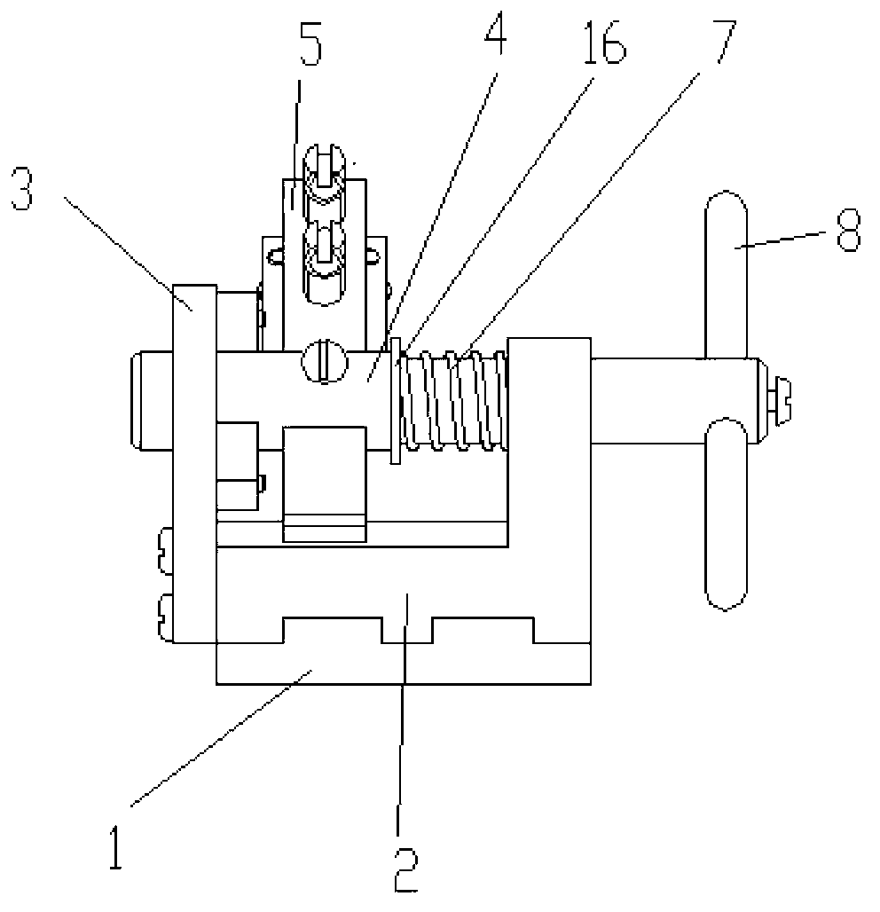
Figure 2 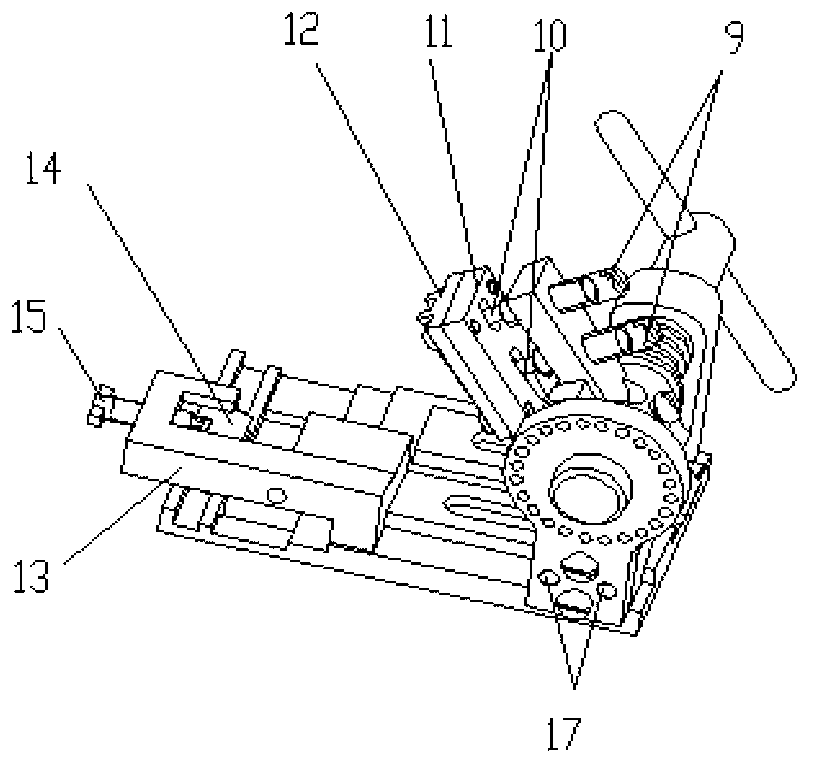
Figure 3
Abstract
Description
technical field
[0001] The invention belongs to welding auxiliary devices, in particular to a general welding auxiliary device suitable for microwave antenna combination welding process. Background technique
[0002] Such as figure 1 As shown, the microwave antenna component 6 is applied to the distance measuring component, and is composed of three parts: a waveguide 6-1, a waveguide seat 6-2 and a waveguide port 6-3. In the free state, the posture and external dimensions of the microwave antenna components cannot be guaranteed after reflow soldering, and the consistency of the antenna components is poor, which affects the microwave transmission performance of the microwave antenna components; the existing welding auxiliary device can only fix the waveguide seat 6-2, the waveguide Tube 6-1 is directly tightened by screws, which is easy to scratch the waveguide; the mouth of the waveguide is lifted by a platform, which cannot play a restraining role, and cannot completely fi...
Examples
Embodiment Construction
[0048] Below in conjunction with accompanying drawing and embodiment the present invention is further described:
[0049] Such as figure 2 with image 3 As shown, the embodiment of the present invention includes a base 1, a bracket 2, an adjustment plate 3, a clamping plate 13, a rotating shaft 4, a sliding plate 5, an upper pressing plate 11 and a lower pressing plate 12; The base 1 moves laterally and is fixed, and the support 2 has a longitudinal shaft hole; the adjustment disc 3 is connected to the side of the support 2, and the adjustment disc 3 has a central hole and positioning holes evenly distributed along the circumference; the rotating shaft 4 is formed by an integral The vertical stepped shaft and the transverse positioning rod are perpendicular to each other. The two ends of the longitudinal stepped shaft are respectively located in the center hole of the adjustment disc and the longitudinal shaft hole of the bracket and are matched with clearance. The two ends ...