Vacuum feeding machine and automatic feeding system

A technology of vacuum feeder and vacuum chamber, which is applied in the direction of transportation, packaging, loading/unloading, etc. It can solve the problems of high power consumption, filter clogging, and slow material conveying speed, so as to improve conveying efficiency, reduce mechanical actions, The effect of reducing mechanical failure

Active Publication Date: 2013-09-25
深圳市杰维工业设备有限公司
View PDF6 Cites 1 Cited by
  • Summary
  • Abstract
  • Description
  • Claims
  • Application Information

AI Technical Summary

Problems solved by technology

[0003] The existing technology has the following three major defects. Defect 1: The material conveying speed is slow, and it can only be conveyed through frequent switching and discharge valve actions, which consumes a lot of power; Defect 2: The material enters the storage tank after vacuum feeding. The filter is frequently in contact with a large amount of materials, and the filters are prone to clogging, and the filter is not cleaned by blowback; defect 3: frequent opening and closing of the discharge valve, which is prone to poor sealing, allowing air to pass through the valve plate and the discharge port High-speed friction between the gaps and damage to the machine

Method used


Image

  • Vacuum feeding machine and automatic feeding system
  • Vacuum feeding machine and automatic feeding system
  • Vacuum feeding machine and automatic feeding system

Examples


Embodiment Construction

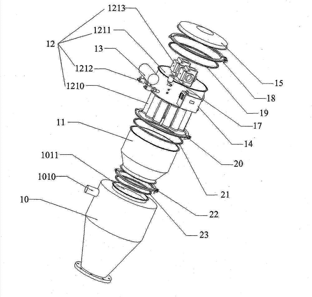
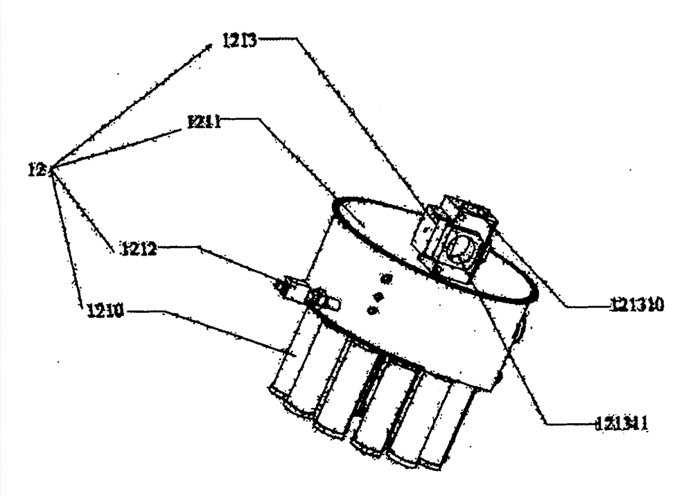
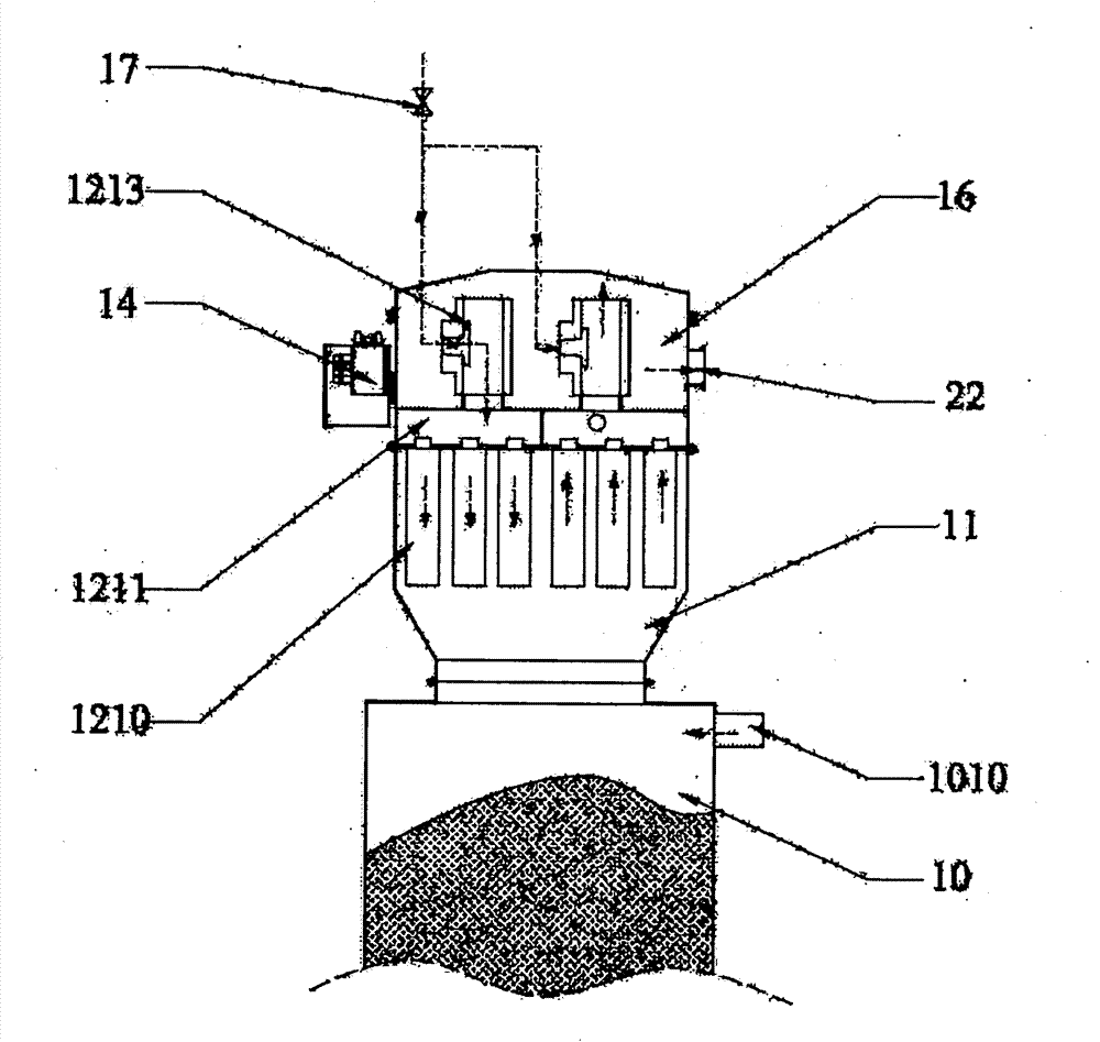
[0040] The vacuum feeder provided by the present invention includes a storage tank 10 , a filter chamber 11 , a controller 14 , a top cover 15 , an air regulating valve 17 , an air cannon 13 and at least two working groups 12 . The concrete structure of each working group 12 is: comprise filter set 1210, control chamber 1211, three-way air control valve 1213 and exhaust valve 1212; The valve 1212 communicates; the three-way air control valve 1213 is provided with a first port, a second port 121310 and a third port 121311 , and the upper end of the control chamber 1211 communicates with the first port of the three-way air control valve 1213 .

[0041] The storage tank 10 is provided with a feed port 1010 and an air intake 1011, and the storage tank 10 communicates with the filter chamber 11 through the air intake 1011; the filter chamber 11 communicates with the lower end of the filter group 1210 of the working group 12; the top cover 15 communicates with the control One end of...


PUM


Abstract

The invention provides a vacuum feeding machine and an automatic feeding system. The vacuum feeding machine comprises a storage tank, a filter chamber, a controller, a top cover, an air regulating valve, an air cannon and at least two working groups, wherein each working group comprises a filter group, a control cavity, a tee pneumatic control valve and an exhaust valve; a feed opening is arranged on the storage tank, and the upper end of the storage tank is communicated with the filter chamber; the filter chambers are communicated with the filter groups; the top cover is fixedly connected with one end of each control cavity, so that a vacuum chamber is formed; the tee pneumatic control valve is accommodated in the vacuum chamber; the exhaust valves are communicated with the air cannon; the tee pneumatic control valves are further communicated with the air regulating valve; and the controller controls the on and off of the air cannon and the on and off of the tee pneumatic control valve of each working group respectively. According to the vacuum feeding machine, the feed opening is directly mounted on the storage tank of a material, so that the material can be prevented from being absorbed on filters excessively; a plurality of the working groups are arranged, and each working group can be independently controlled by the controller, so that the material can be conveyed continuously, and the conveying efficiency is improved greatly; and the mechanical device is optimized, mechanical faults are reduced, and the operation is convenient.

Description

technical field [0001] The invention relates to the field of powder material transportation, in particular to a vacuum feeding machine and an automatic feeding system. Background technique [0002] At present, the vacuum feeding widely used in the market adopts intermittent vacuum feeding, refer to Figure 5 , that is, the vacuum is generated by the vacuum generator or the negative pressure fan pump to suck the material into the receiving tank, the air and the material are separated through the filter, the time of pumping and discharging is set, and the discharge valve of the feeding machine is controlled by the controller The switch discharges the material to the storage tank. Since the vacuum generator or the negative pressure fan must be stopped during the material discharge process, at the same time, the filter is blown back by the air cannon to make the material adsorbed on the filter fall off, forming a circular operation. . [0003] The existing technology has the fo...

Claims


Application Information

Patent Timeline
Patent Type & Authority Applications(China)
IPC IPC(8): B65G65/32B65G69/18
Inventor 武员
Owner 深圳市杰维工业设备有限公司
Why Eureka
Try Eureka