Eureka AIR delivers breakthrough ideas for toughest innovation challenges, trusted by R&D personnel around the world.

Carrier conveying device

A technology for conveying devices and vehicles, applied in the direction of conveyor objects, transportation and packaging, etc., can solve the problems that it is difficult for vehicles to abut against vehicles, affect the accuracy of vehicles, the assembly accuracy of assembly machines, and the impact on stability, etc. , to achieve the effect of compact structure, convenient layout, stable and precise conveying

Active Publication Date: 2015-12-30
MAIDER MEDICAL IND EQUIP
View PDF8 Cites 8 Cited by
  • Summary
  • Abstract
  • Description
  • Claims
  • Application Information

AI Technical Summary

Problems solved by technology

Although such a conveying method realizes continuous conveying, the carrier and the carrier are against each other. With the increase of the carriers on the guide rail, it is difficult to ensure a good contact between the carriers. If there is a deviation in the position of one of the carriers, it will affect the accuracy of the position of the carrier on the entire conveyor rail, which will affect the assembly accuracy and stability of the assembly machine

Method used


Image

  • Carrier conveying device
  • Carrier conveying device
  • Carrier conveying device

Examples


Embodiment 1

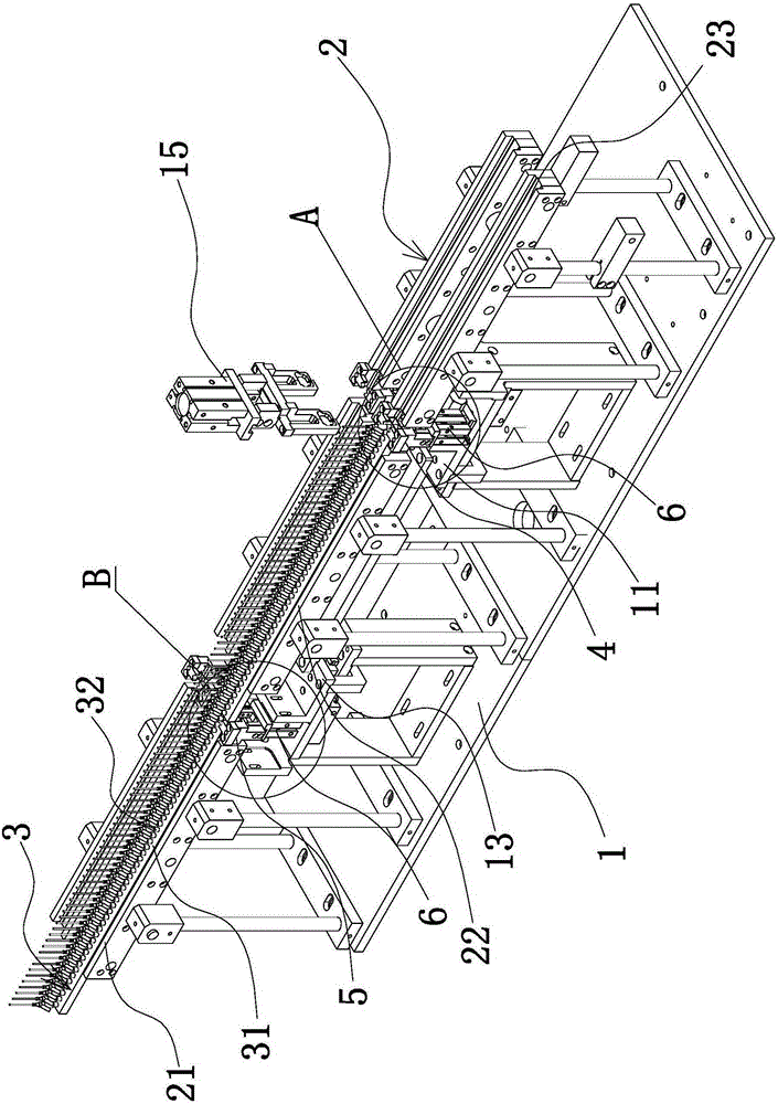
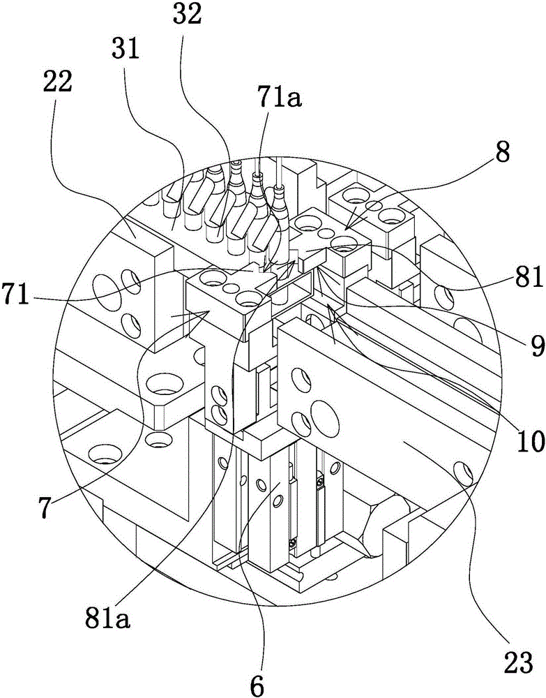
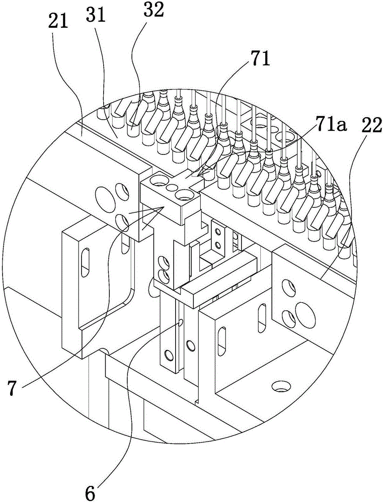
[0030] Such as figure 1 As shown, the conveying device of the carrier 3 includes a frame 1 and a guide rail 2 arranged on the frame 1 and extending in a straight line direction. The guide rail 2 is provided with a chute along its length direction, and several long rails are slidably arranged in the chute. Strip carrier 3. Of course, the carrier 3 can also be in other shapes. Several carriers 3 are arranged in sequence along the length direction of the guide rail 2 and can translate along the guide rail 2 . The carrier 3 includes a long slider 31, the cross section of the slider 31 is rectangular, the ends of the sliders 31 of two adjacent carriers 3 are against each other, and the upper surface of the slider 31 is uniform along the length direction of the slider 31. Several positioning columns 32 are arranged at intervals. The positioning post 32 can be used to sheath the needle sheath, sheath, etc. on it, so as to realize the delivery of the needle sheath, sheath, etc. Th...


PUM


Abstract

The invention provides a carrier conveying device and belongs to the technical field of medical accessory assembling machines. The technical problem that an existing carrier conveying device is low in conveying precision is solved. The carrier conveying device comprises a machine frame and a guide rail arranged on the machine frame and extending in the linear direction. The guide rail is provided with a plurality of carriers which can horizontally move along the guide rail. The carriers are sequentially arranged in the length direction of the guide rail. The machine frame is provided with a first clamping jaw capable of being opened and closed. The first clamping jaw can achieve relative positioning with one carrier when closed. The machine frame is provided with a pushing mechanism capable of pushing the other carriers towards the first clamping jaw. The machine frame is further provided with a first driving mechanism capable of driving the first clamping jaw to move back and forth in the length direction of the guide rail. The carrier conveying device has the advantages of being high in conveying precision, compact in structure and the like.

Description

technical field [0001] The invention belongs to the technical field of medical accessory assembly machines, and relates to a carrier conveying device. Background technique [0002] With the development of science and technology, the assembly of medical accessories has been automated, and the medical accessories are assembled on the assembly machine. During assembly, the accessories are generally placed on the carrier, and the carrier can be moved to each assembly station on the frame of the assembly machine to realize the assembly of the accessory and other accessories, and finally form the required medical accessories. Accurate assembly is one of the most important indicators of the medical accessories assembly machine, and the transportation of the carrier is completed by the conveying device set on the frame, so the conveying device is required to have high accuracy and stability . [0003] Disclose a kind of conveying device (application number: 201120071097.7) of the ...

Claims


Application Information

Patent Timeline
IPC IPC(8): B65G47/90B65G47/74
Inventor 林军华
Owner MAIDER MEDICAL IND EQUIP
Why Eureka
Eureka Blog
Learn More