Vibrating bunker

A technology of vibrating hopper and material area, applied in the direction of vibrating conveyor, conveyor, transportation and packaging, etc., can solve the problems of inability to guarantee the continuous conveying of the regulator shell, slow speed and low production efficiency, and achieve high practical value. , The effect of improving assembly speed and simple structure

Inactive Publication Date: 2006-03-08
浙江东美智能设备有限公司
View PDF0 Cites 8 Cited by
  • Summary
  • Abstract
  • Description
  • Claims
  • Application Information

AI Technical Summary

Problems solved by technology

Since there is only one discharge chute, the regulator casing enters the discharge chute from the inclined plane at a slow speed, which cannot ensure that the regulator casing is evenly and continuously transported to the assembly tray, and the production efficiency is low

Method used


Image

  • Vibrating bunker
  • Vibrating bunker

Examples


Embodiment Construction

[0020] The following is an example of a vibrating hopper for monolithic processing of the regulator housing on the infusion set. Depend on figure 1 It can be seen from the figure that the main part of the vibrating hopper is mainly composed of a base 1 and a cylindrical side wall 3 fixed together, and a spiral slope 2 is provided on the base 1 along the side wall 3 .

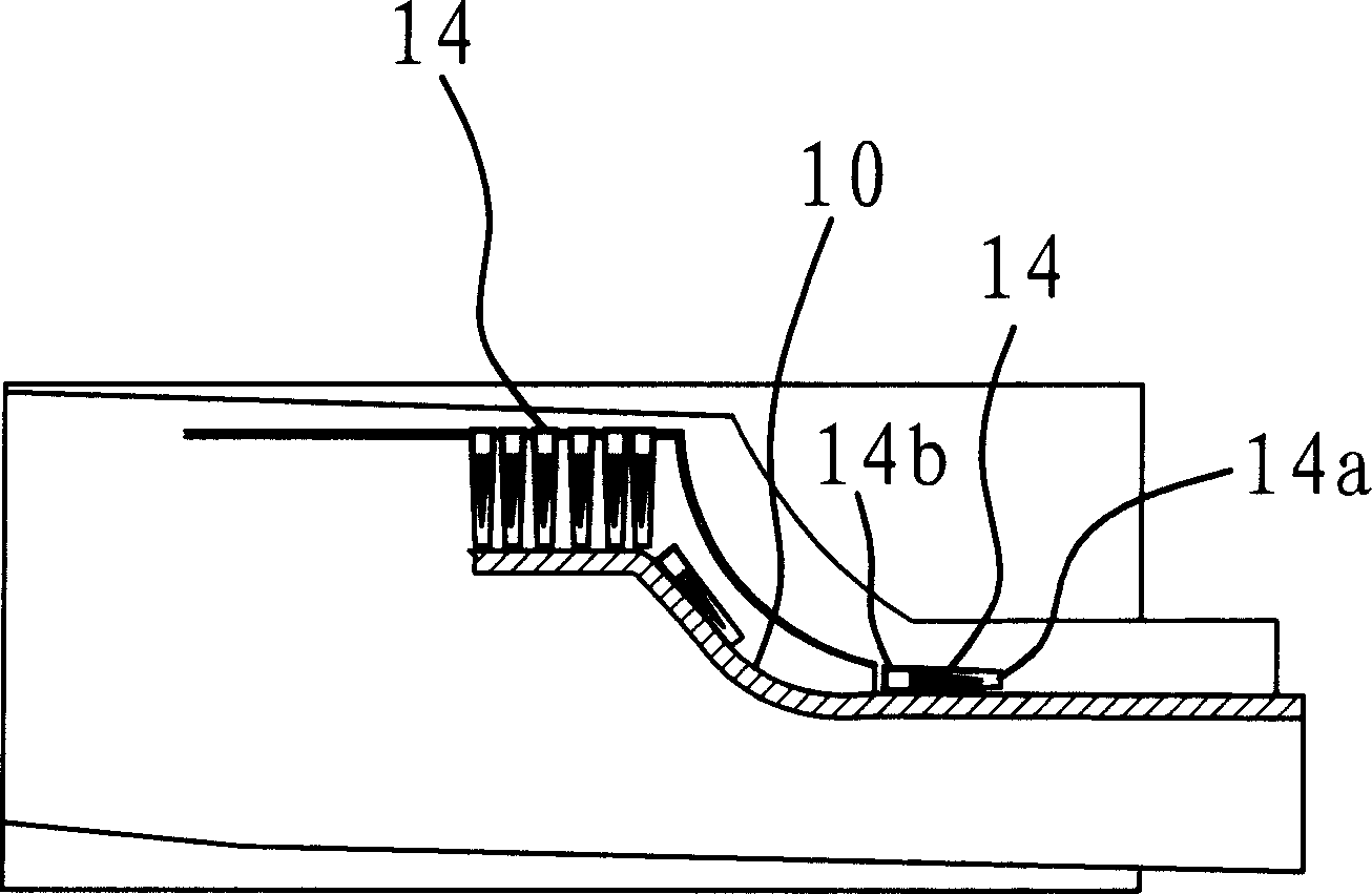
[0021] Such as figure 1 As shown, a discharge port 9 is also provided on the side wall 3, and at least two discharge troughs 4 arranged side by side are arranged between the discharge port 9 and the inclined surface 2, and the width of the discharge chute 4 is between the regulator shell The size of the housing head 14a of the body 14 is between the size of the housing and the size of the housing tail 14b. In this embodiment, considering the overall compact structure of the vibrating hopper and the actual requirement of the material delivery speed, the number of discharge troughs 4 is two. The two ends of the...


PUM


Abstract

A sort of vibrating hopper is disclosed, which overcomes the problem of present vibrating hopper, which caní»t uniformly and continuously transform materials to packing site. The hopper comprises a base and a tube-like side wall. A spiral oblique face is provided on the base, an outlet is provided at the side wall and between the oblique face and the outlet are provided with at least two parallel discharge channels. The two ends of the channel are respectively the inlet of material that is near to the highest part of the oblique face and the discharge end that is near the outlet. Advantages: continuous and uniform transfer of material; high assembling speed, simple and compact structure.

Description

technical field [0001] The invention belongs to the technical field of automatic assembly machines, in particular to a vibrating hopper on an automatic assembly machine. Background technique [0002] The vibrating feeder is a device that continuously conveys loose bulk materials from the hopper to the assembly machinery, and can be widely used in the transportation of medicine, chemical industry, metallurgy, coal, building materials and other industries. The main part of the vibrating feeder is a vibrating hopper, which has two types of mechanical vibration and electromagnetic vibration. The vibrating hopper is mainly composed of a solidly connected base and a cylindrical side wall. There is a spiral slope on the base. When the vibrating feeder is working, the vibrating hopper vibrates, so that the materials in the hopper can be vibrated. It goes up along the above-mentioned spiral surface on the base, and comes out from the discharge port, and is finally transported to the...

Claims


Application Information

Patent Timeline
Patent Type & Authority Applications(China)
IPC IPC(8): B65G27/02
Inventor 王兴章
Owner 浙江东美智能设备有限公司
Why Eureka
Try Eureka