Micro needle tip with orientation structure and method thereof for continuously conveying liquid

A micro-needle tip and orientation technology, applied in the field of micro-nano manufacturing, can solve problems such as difficulty in wide applicability, inability to transport large droplets, and inability to transfer droplets successfully, achieving high success rate and continuous transportation , the effect of transporting a small amount of liquid

Active Publication Date: 2015-11-11
SHENZHEN TSIMEC CO LTD
View PDF4 Cites 9 Cited by
  • Summary
  • Abstract
  • Description
  • Claims
  • Application Information

AI Technical Summary

Problems solved by technology

That is to say, when the size is as small as the micro-nano scale, the droplet will not stay at the tip. Therefore, if the tip of the microneedle tip directly touches the substrate at this time, it is impossible to transport the large droplet on the microneedle tip. of
Although the traditional needle tip transfer method has the advantage of being extremely simple, it cannot successfully transfer droplets because surface tension replaces gravity as a controlling factor at a micro scale, and thus has been eliminated by some modern industrial fields that are rapidly becoming miniaturized (non Contact jet dispensing—the future dispensing technology (English)[J].Semiconductor Technology,2004,03:67-70.)
Even if these technologies can be improved, such as laying a thin film of soft material on the substrate, when piercing with a needle tip, the film will come into contact with the droplet of the microneedle tip to attract it, or use glue with strong adhesion and large hysteresis, etc. It is difficult to have a wide range of applicability, and there will be problems in the transfer that either cannot be transferred, or most of the droplets will be transferred at once, that is, the problem of poor uniformity and continuity, which is not suitable for ultra-precision manufacturing

Method used


Image

  • Micro needle tip with orientation structure and method thereof for continuously conveying liquid
  • Micro needle tip with orientation structure and method thereof for continuously conveying liquid
  • Micro needle tip with orientation structure and method thereof for continuously conveying liquid

Examples


Embodiment Construction

[0037] The present invention proposes a microneedle tip with an orientation structure and a method for continuously transporting liquid thereof. The present invention will be described in detail below with reference to the accompanying drawings and specific embodiments.

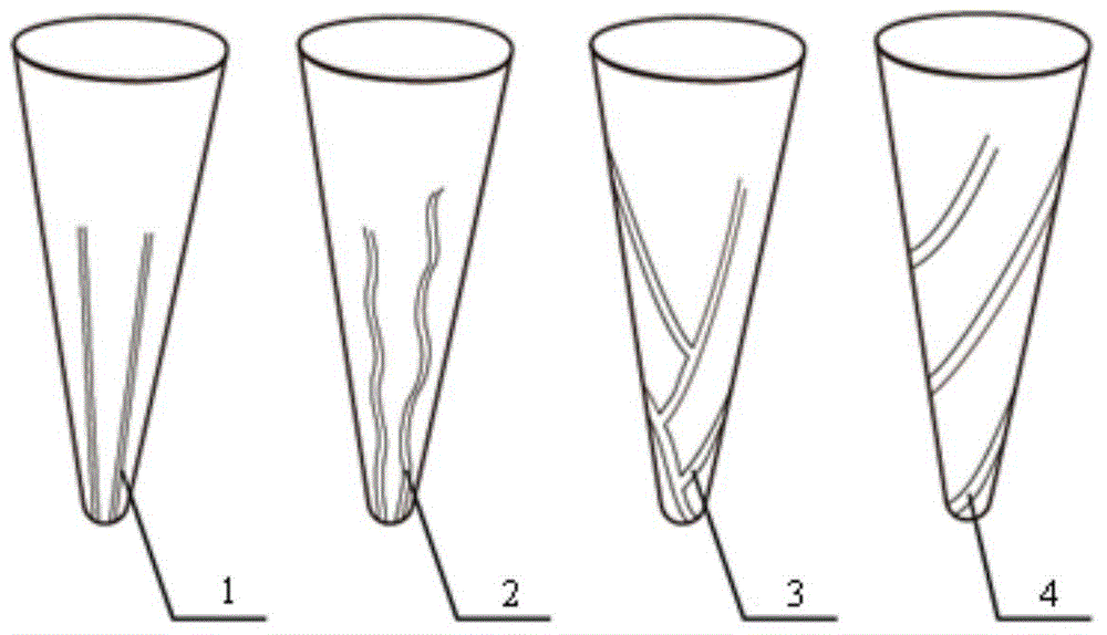
[0038] The present invention proposes a micro-needle tip with an orientation structure. The micro-needle tip is tapered with a thin tip and a thick root. The surface of the micro-needle tip is made with an oriented micro-nano groove-like structure. The micro-nano groove-like structure penetrates to the micro-nano The tip of the needle tip, the radius of the curvature circle of the tip of the micro-needle tip is not more than 20 microns, the average width and average depth of the micro-nano groove-like structure are between 20 nanometers and 5 microns, the micro-nano groove-like structure on the surface of the micro-needle tip The orientation is specifically that the axial direction of the micro-nano-groove-lik...


PUM


Abstract

The invention discloses a micro needle tip with an orientation structure and a method thereof for continuously conveying liquid, belonging to the technical field of micro-nano manufacture. The tapered micro needle tip has a thin tip and a thick root. An oriented micro-nano groove-shaped structure is manufactured on the surface of the micro needle tip. Liquid drops are put on or supplemented to the micro needle tip with the micro-nano groove-shaped structure. Under the action of surface tension, the liquid drops automatically move to a liquid storage position of the micro needle tip. Under the control of a mobile device, the micro needle tip with the liquid drops moves to a target position. Under the action of capillary force of the micro-nano groove-shaped structure on the surface of the micro needle tip, liquid drops flow downward along the micro needle tip to a substrate of the target position. The liquid drops are solidified and stacked on the substrate of the target position so as to form a pattern or a stereostructure. The micro needle tip can be manufactured precisely from bottom to top. Compared with the prior art, the micro needle tip has the advantages of good continuity, controllable size, simple device, high resolution, and broad application range.

Description

technical field [0001] The invention belongs to the technical field of micro-nano manufacturing, and in particular relates to a micro-needle tip with an orientation structure and a method for continuously transporting liquid thereof. Background technique [0002] In today's era, a large number of electromechanical devices are developing in the direction of miniaturization, which makes various devices integrate more functions while being lightweight and portable. The miniaturization of devices puts forward higher requirements for related technologies such as manufacturing, packaging, and testing. Photolithography technology can produce microstructures with a minimum size of about 1 micron. Electron beam exposure technology further improves the resolution and can produce nanostructures with a scale of tens of nanometers. However, these traditional top-down manufacturing methods have certain limitations, such as the complicated process of manufacturing three-dimensional struct...

Claims


Application Information

Patent Timeline
Patent Type & Authority Applications(China)
IPC IPC(8): B81B1/00
Inventor 董华来杨兴郑泉水
Owner SHENZHEN TSIMEC CO LTD
Why Eureka
Try Eureka