

Roller blind fixing seat and window frame connection device
A connecting device and fixing seat technology, which is applied in the direction of hanging curtains, window decorations, shading screens, etc., can solve the problem of single case method and cannot meet the needs of different customers, so as to improve flexibility, facilitate replacement and adjustment, adaptable effect
- Summary
- Abstract
- Description
- Claims
- Application Information
AI Technical Summary
Problems solved by technology
Method used
Image

Examples
Embodiment 1
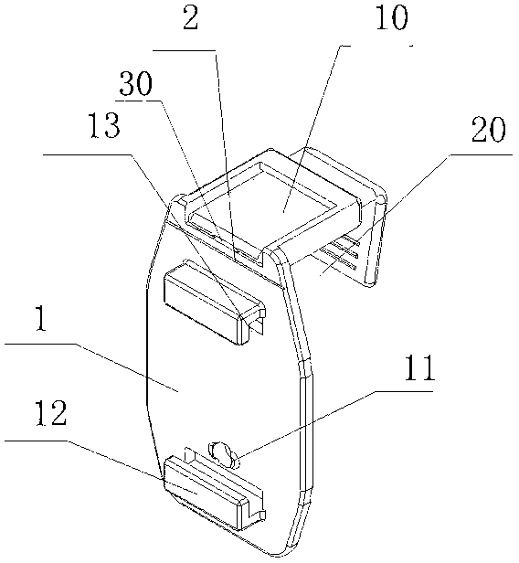
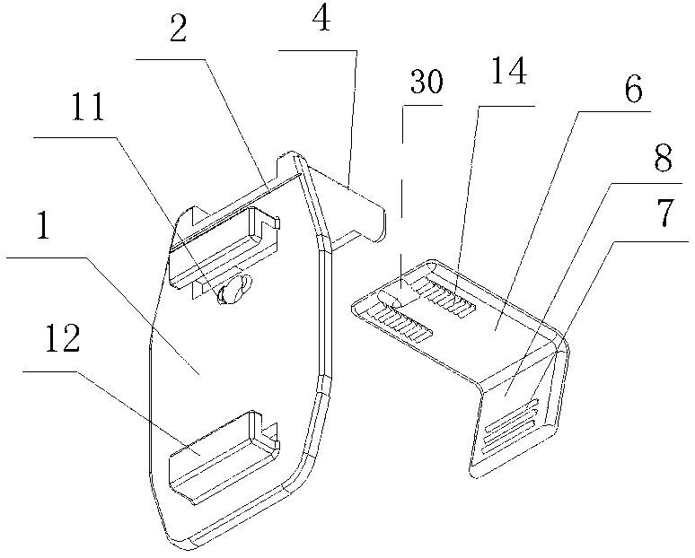
[0023] Such as figure 1 with 2 As shown in and 3, a connection device between a roller blind fixing seat and a window frame includes a long connecting body 1, and an adjustable clamping part 10 is provided at one end of the connecting body 1, and the adjustment range of the clamping part 10 is greater than the width of the window frame. The clamping part 10 includes a clamping body 4 and an adjusting body 9 , the clamping body 4 is integrally formed with the connecting body 1 , the clamping body 4 is located at the upper end of the connecting body 1 , and the clamping body 4 is perpendicular to the connecting body 1 . The adjusting body 9 is an "L"-shaped member, the angle between the two connecting surfaces of the adjusting body 9 is an acute angle, and one of the connecting surfaces of the adjusting body is the first connecting surface 6, and the first connecting surface 6 and the clip The tight body 4 is connected, and the other connection surface of the adjustment body 9...
Embodiment 2
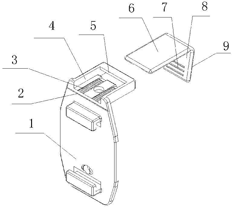
[0027] Such as Figure 5 with 6 As shown in and 7, a connection device between a roller blind fixing seat and a window frame includes a long connecting body 1, and an adjustable clamping part 10 is provided at one end of the connecting body 1, and the adjustment range of the clamping part 10 is greater than the width of the window frame. The clamping part 10 includes a clamping body 4 and an adjusting body 9 , the clamping body 4 is integrally formed with the connecting body 1 , the clamping body 4 is located at the upper end of the connecting body 1 , and the clamping body 4 is perpendicular to the connecting body 1 . A supporting plate 17 is integrally formed at the lower end of the connecting body 1 , the supporting plate 17 is perpendicular to the connecting body 1 , and the extending direction of the clamping body 4 is opposite to that of the supporting plate 17 . A fixing protrusion 18 is provided on the supporting plate 17 , and the fixing protrusion 18 is parallel to...
PUM
 Abstract
Description
Claims
Application Information