

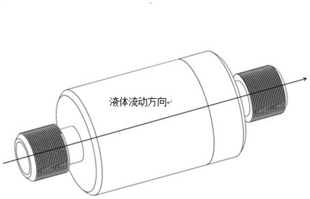
Flow regulating valve
A technology of flow regulating valve and casing, applied in the direction of valve device, sliding valve, separation method, etc., can solve the problems of carrying capacity influence, inability to guarantee, large center of mass offset, etc., to improve work efficiency and facilitate replacement and adjustment.
- Summary
- Abstract
- Description
- Claims
- Application Information
AI Technical Summary
Problems solved by technology
Method used
Image

Examples
Embodiment 1
[0029] Embodiment 1. Regulating pipeline, such as Figure 10 shown.
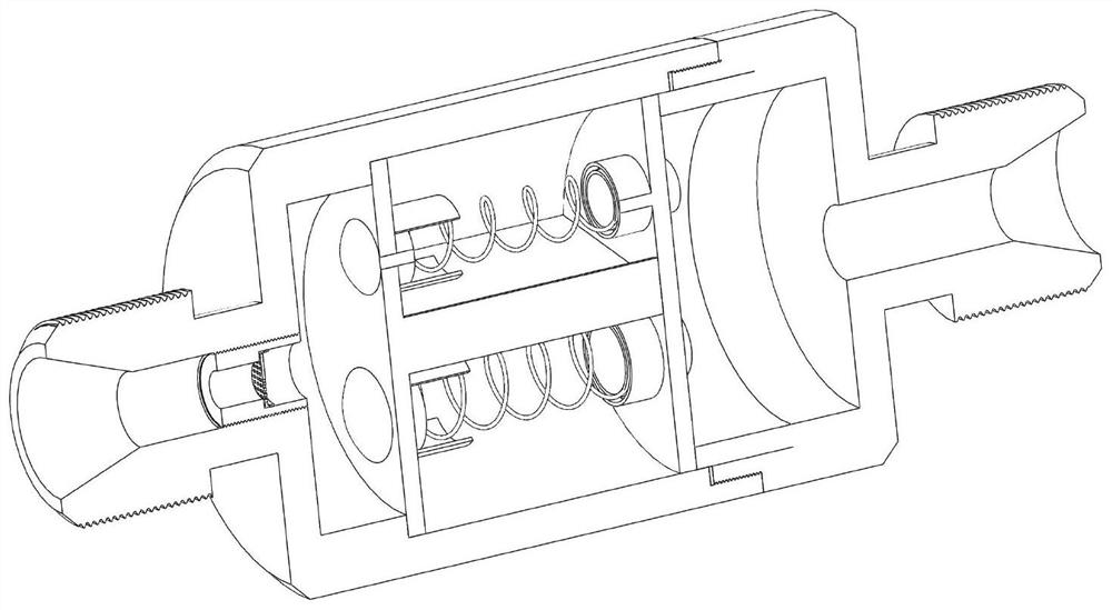
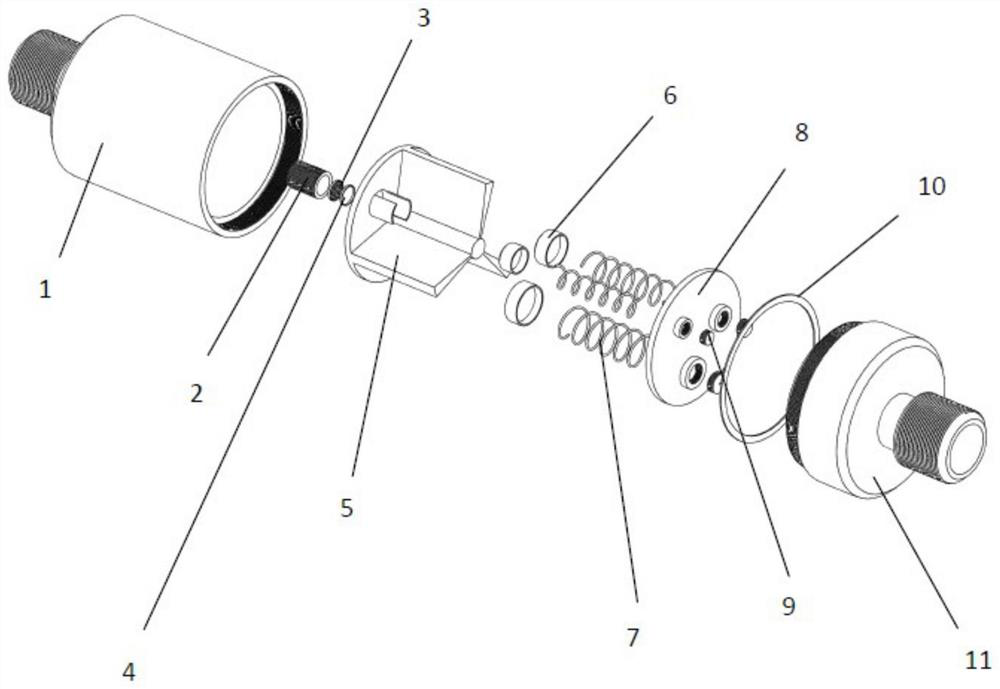
[0030] During the pipeline liquid flow test, the back pressure (the pressure at the back end, usually used to describe the pressure opposite to the flow direction received by the fluid discharged from the system at the outlet or the secondary side) when the flow is changed and adjusted should meet the pressure above 1MPa (In order to avoid the formation of cavitation in the pipeline, affecting the test pressure parameters). The design of the invention can adapt to switching under three different flow rates to ensure that the back pressure is above 1MPa. A variety of flow adjustments can also be designed according to flow requirements. The spool part of this design is divided into three independent spools, which are opened sequentially according to different flows.
[0031] Connect the system pipelines to the system flow table, and connect the pipelines, hand valves, pressure gauges, flow meters, and flow r...
Embodiment 2
[0033] Utilizing the characteristics of the structure of the invention to regulate the flow rate, the output flow rate of the two storage tanks is guaranteed to be consistent. The storage tank is used as a liquid storage container for the liquid rocket. During use, the liquid in the liquid chamber is squeezed into the system pipeline by the gas squeezing the metal diaphragm. Due to the difference (thickness, design deviation) of the metal diaphragm of the storage tank, the two There is a difference in side overturning pressure, and long-term discharge is likely to cause differences in the remaining volumes of the two storage tanks, resulting in system deflection. By introducing the invention into the system pipeline, the flow can be adjusted by adjusting the opening of the valve cores on both sides. To carry out a simultaneous discharge test study in a tank, see Figure 11As shown, firstly, the upper and lower limit difference of the titanium alloy tank discharge under differ...
PUM
 Abstract
Description
Claims
Application Information