Reactive muffler structure with combination of perforated pipes and narrow-slit resonant cavities

A technology of resistant noise reduction and perforated tubes, which is applied in the direction of noise reduction devices, machines/engines, mechanical equipment, etc., can solve the problems of general noise reduction effect, enhanced acoustic impedance, high pressure, etc., and achieve simple manufacturing process and enhanced acoustic impedance , the effect of small pressure loss

Active Publication Date: 2013-09-25
SHANDONG UNIV
View PDF6 Cites 5 Cited by
  • Summary
  • Abstract
  • Description
  • Claims
  • Application Information

AI Technical Summary

Problems solved by technology

[0004] The perforated tube muffler structure is a commonly used resonant muffler structure at present. The straight through perforated tube structure has a very strong guiding effect on the airflow, and the pressure loss is small. However, since most of the airflow directly passes through the straight tube, it cannot expand The cavity is fully released, and the high-frequency band will fail, so the noise reduction effect is general; for the cross-flow perforated tube structure, the airflow must all flow out through the small holes on the perforated tube, which enhances the acoustic impedance, and there is no noise in the high-frequency band. In case of failure, the noise reduction effect is better than that of the straight-through perforated pipe muffler, but because the air flow must all flow through the small holes on the pipe, a relatively high pressure loss is caused.

Method used


Image

  • Reactive muffler structure with combination of perforated pipes and narrow-slit resonant cavities
  • Reactive muffler structure with combination of perforated pipes and narrow-slit resonant cavities

Examples


Embodiment Construction

[0018] The present invention will be further described below in conjunction with the drawings and embodiments.

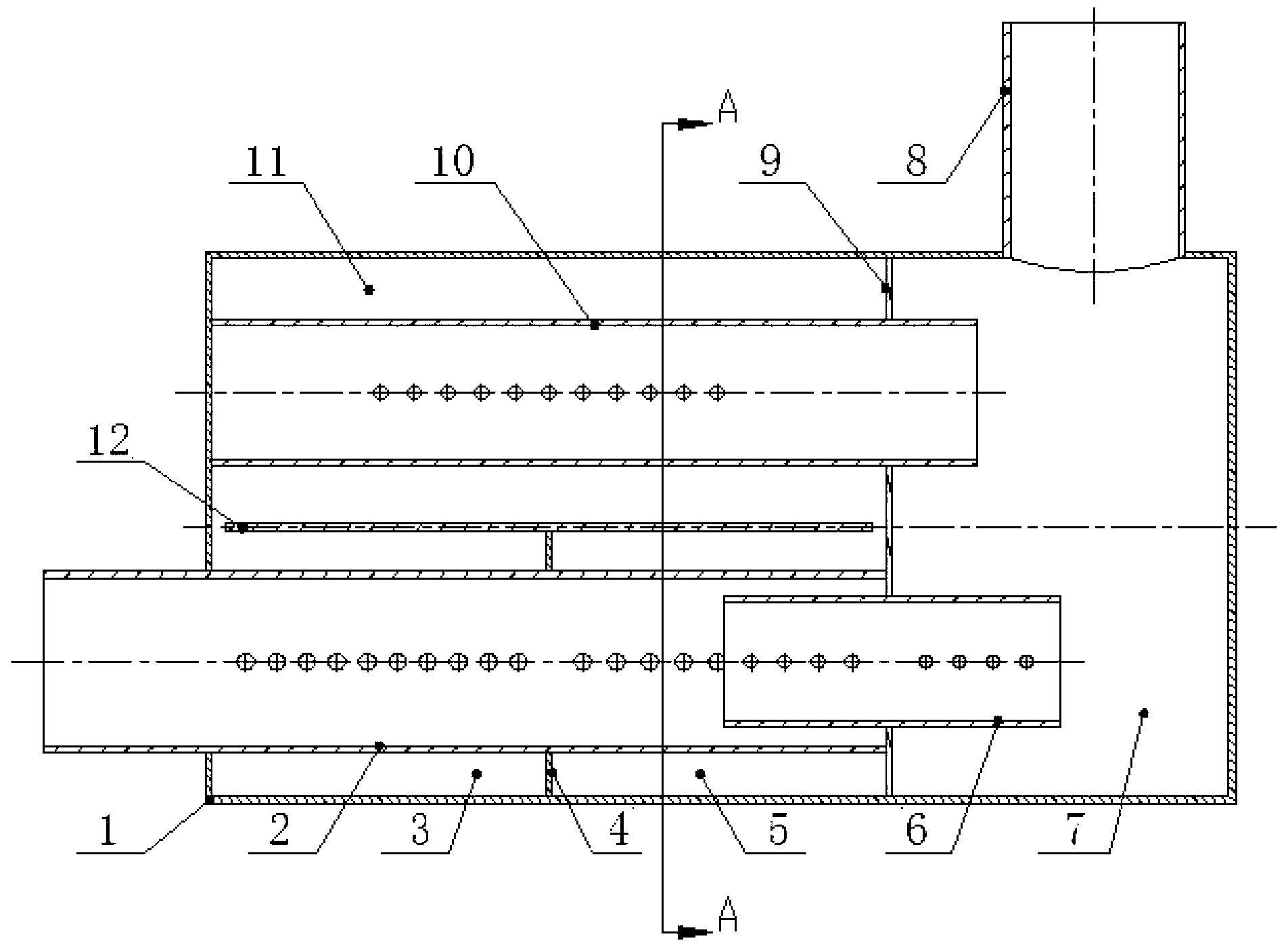
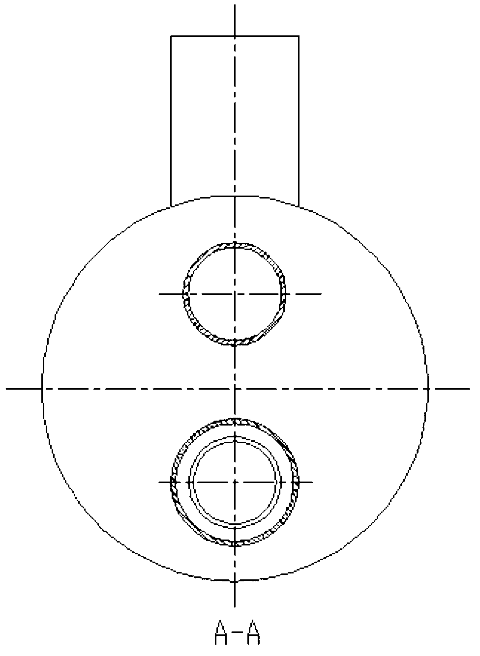
[0019] figure 1 As shown, the described structure of a resistant muffler combining a perforated tube and a narrow slot resonant cavity includes a cylinder body 1, an air inlet tube 2, an air outlet tube 8, a straight-through perforated tube 6, a cross-flow perforated tube 10, a transverse partition 12, and a longitudinal Partition plate I4 and longitudinal partition plate Ⅱ9; the cylinder body 1 is divided into four independent chambers through horizontal partition plate 12, longitudinal partition plate Ⅰ4 and longitudinal partition plate Ⅱ9: chamber Ⅰ3 and chamber Ⅱ5 , Chamber III11 and chamber IV7; the air inlet perforated pipe 2 and the straight-through perforated pipe 6 are coaxially offset, and the chamber IV7 is directly connected to the inlet pipe 2 through the straight-through perforated pipe 6; the inlet perforated pipe 2 is The longitudinal partition 4 is div...


PUM


Abstract

The invention discloses a reactive muffler structure with combination of perforated pipes and narrow-slit resonant cavities. The reactive muffler structure with the combination of the perforated pipes and the narrow-slit resonant cavities comprises a cylinder body, an air inlet perforated pipe and a transverse flow perforated pipe, wherein the cylinder body is divided into a left chamber and a right chamber by a longitudinal separating plate II, the left chamber is divided into an upper chamber and a lower chamber by a transverse separating plate, the upper chamber and the lower chamber are communicated, the lower chamber is divided by a longitudinal separating plate I, the air inlet perforated pipe penetrates through the lower chamber and the longitudinal separating plate I, the transverse flow perforated pipe penetrates through the upper chamber to reach the interior of the right chamber, and the top of the right chamber is communicated with an air outlet pipe. The reactive muffler structure with the combination of the perforated pipes and the narrow-slit resonant cavities is simple and reasonable in structure, comprehensively utilizes the silencing characteristic of the perforated pipes and structures of the narrow-slit resonant cavities, is low in pressure loss, high in silencing capacity, and obviously good in silencing effect of a low-frequency stage which corresponds to the ignition frequency of a common engineering machinery engine.

Description

[0001] Technical field [0002] The invention relates to a novel muffler structure, in particular to a resistant muffler structure combined with a perforated tube and a narrow slot resonance cavity. Background technique [0003] Resistant muffler is currently one of the main ways to effectively control engine exhaust noise in the field of construction machinery. The design level of muffler directly affects the positioning of China's construction machinery in the global construction machinery field, effectively controlling noise pollution, and affecting the national production and Life is of great significance; the performance of the muffler is mainly reflected in two aspects of silencing performance and aerodynamic performance. Its effective evaluation indicators are transmission loss and pressure loss; while increasing the transmission loss of the muffler, ensure that its pressure loss is in the engine Within the required range is the core requirement of muffler design, and it is...

Claims


Application Information

Patent Timeline
Patent Type & Authority Applications(China)
IPC IPC(8): F01N1/02
Inventor 周以齐白儒王丽薛源
Owner SHANDONG UNIV
Why Eureka
Try Eureka