There is a limited voltage of the rod of the end -faced piston piston.

A technology of auxiliary brake and valve device, applied in the direction of engine control, machine/engine, mechanical equipment, etc., can solve the problems such as the inability to adjust the pressure of the adjusting screw, the lag in the braking action of the auxiliary brake valve, and the easy deformation and fracture, and achieve effective Adjust the exhaust back pressure, increase the exhaust back pressure value, and cooperate with the effect of good sealing

Active Publication Date: 2016-02-03
ZHEJIANG EASUN PNEUMATIC SCI & TECH
View PDF8 Cites 0 Cited by
  • Summary
  • Abstract
  • Description
  • Claims
  • Application Information

AI Technical Summary

Problems solved by technology

[0003] The pressure-limiting and deflated auxiliary brake valve device in the prior art relies on the cylinder or the vacuum booster cylinder to push and pull the drive shaft to deflect to cause the butterfly plate to deflect. The drive shaft is inserted into the butterfly plate and fixed with rivets. , the rivet is easily deformed and broken under a large pressure, and the butterfly cannot realize its effective movement
[0004] Chinese Patent Nos. 200710137250.X and 200810126049.6 disclose a kind of exhaust brake, which includes a valve body, a disc, a support rod, a support sleeve, a pressure reducing valve, a spring and an adjusting screw. Release the excess pressure to ensure the stability of the working pressure, but when the pressure reducing valve is opened to adjust the pressure, it will cause hot gas to surround the spring, and the very high temperature will easily cause the spring to fail; moreover, the pressure reducing valve, the pressure plate and the adjusting screw have no guiding design, and the combination is not good. Stable, the offset of the pressure plate makes the adjustment screw unable to adjust the proper pressure; in addition, the pressure plate and the pressure reducing valve are easy to rotate, causing the spring torsion and causing the spring to break and fail
When the butterfly plate is closed and the engine exhaust gas is discharged into the intake chamber of the valve body, a part of the gas will inevitably enter the housing of the pressure regulating device, which hinders the reciprocating movement of the tappet and cannot effectively control the exhaust back pressure.
At the same time, due to the high temperature of the exhaust gas of the engine, the closed structure prevents the inner chamber of the pressure regulating device from dissipating heat, and the continuous high temperature will cause the pressure limiting spring to be deformed by heat, or even fail, and the braking effect of the auxiliary brake valve is seriously delayed, and the sensitivity is greatly reduced

Method used


Image

  • There is a limited voltage of the rod of the end -faced piston piston.
  • There is a limited voltage of the rod of the end -faced piston piston.
  • There is a limited voltage of the rod of the end -faced piston piston.

Examples


Embodiment Construction

[0036]Several preferred embodiments of the present invention will be described in detail below with reference to the accompanying drawings, but the present invention is not limited to these embodiments. The present invention covers any alternatives, modifications, equivalent methods and schemes made on the spirit and scope of the present invention. In order to provide the public with a thorough understanding of the present invention, specific details are set forth in the following preferred embodiments of the present invention, but those skilled in the art can fully understand the present invention without the description of these details. In addition, well-known methods, procedures, processes, components, etc. have not been described in detail in order to avoid unnecessary confusion to the essence of the present invention.

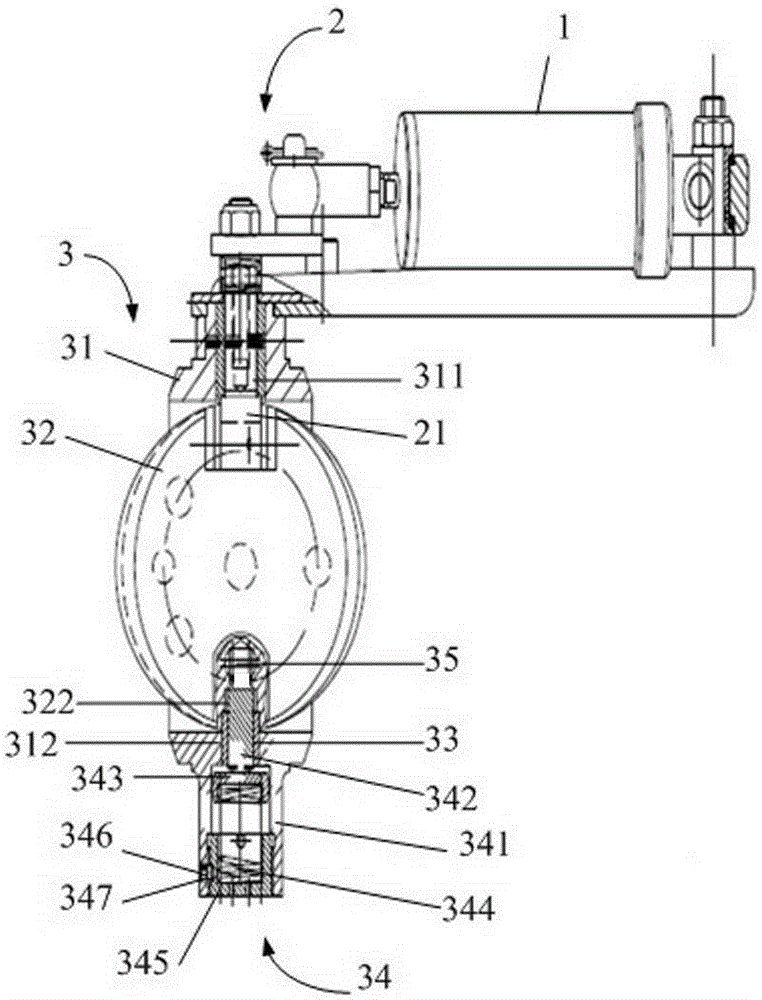
[0037] Please refer to figure 1 The schematic diagram of the auxiliary brake valve of the present invention, the auxiliary brake valve is mainly compose...


PUM


Abstract

The invention relates to a pressure-limiting air escape auxiliary brake valve device with a piston tappet with an end face. The pressure-limiting air escape auxiliary brake valve device comprises a valve body, a disc, a support device, a pressure regulator and a pressure relief opening device, a fixing through hole is arranged on the valve body, a driving shaft penetrates through the fixing hole of the valve body to fix the disc in the valve body, a fixing notch and a support groove are arranged on the disc, the pressure regulator comprises the piston tappet which is a cylinder, one end of the piston tappet passes through the support device to extend into the support groove in a projecting manner, the piston tappet is arranged between the support device and the support groove and receives different air pressure transmitted by the pressure relief opening device for movement, and one end of the piston tappet inserted into the support groove serves as an end face. The pressure-limiting air escape auxiliary brake valve device is compact in structure, and movement stroke of the piston tappet is effectively controlled; exhaust backpressure values of an engine at medium and low speeds are decreased; and small resistance during reciprocation of the piston tappet is guaranteed, an inner spring is prevented from failure caused by high temperature, and accordingly the service life of the auxiliary brake valve device is longer.

Description

technical field [0001] The invention relates to an auxiliary braking device, in particular to a pressure-limiting and air-releasing auxiliary braking valve device for a vehicle with an end face piston tappet. Background technique [0002] The pressure-limiting and air-leakage auxiliary brake valve device is an auxiliary braking device for vehicles, especially suitable for commercial vehicles. Vehicle brake failure to ensure driving safety. [0003] The pressure-limiting and deflated auxiliary brake valve device in the prior art relies on the cylinder or the vacuum booster cylinder to push and pull the drive shaft to deflect to make the butterfly plate deflect. The drive shaft is inserted into the butterfly plate and fixed with rivets, and the force of the drive shaft deflection acts on the rivet , The rivet is easily deformed and broken under a large compressive force, and the butterfly cannot realize its effective movement. [0004] Chinese Patent Nos. 200710137250.X and ...

Claims


Application Information

Patent Timeline
Patent Type & Authority Patents(China)
IPC IPC(8): F02D9/06
Inventor 褚志强吴和文王斌钱利春李清清陈磊磊
Owner ZHEJIANG EASUN PNEUMATIC SCI & TECH
Why Eureka
Try Eureka