Spring end cover of exhausting brake butterfly valve and exhausting brake butterfly valve

A technology of exhaust brake and butterfly valve, which is applied in the direction of engine control, machine/engine, mechanical equipment, etc., can solve the problems of reduced sensitivity, lagging and failure of exhaust brake braking effect, etc., to prevent pollution, prevent random disassembly, The effect of preventing failure

Inactive Publication Date: 2011-09-14
ZHEJIANG EASUN PNEUMATIC SCI & TECH
View PDF6 Cites 0 Cited by
  • Summary
  • Abstract
  • Description
  • Claims
  • Application Information

AI Technical Summary

Problems solved by technology

[0005] The blockage on the existing pressure regulating device and the casing of the pressure regulating device are fully enclosed structures
When the butterfly plate is closed and the engine exhaust gas is discharged into the intake chamber of the valve body, a part of the gas will inevitably enter the housing of the pressure regulating device, which hinders the reciprocating movement of the tappet and cannot effectively control the exhaust back pressure.
At the same time, due to the high temperature of the exhaust gas of the engine, the closed structure prevents the inner cavity of the pressure regulating device from dissipating heat, and the continuous high temperature will cause the pressure limiting spring to be deformed by heat, or even fail, and the braking effect of the exhaust brake is seriously delayed, and the sensitivity is greatly reduced
[0006] In addition, the blockage on the existing exhaust brake valve is directly threaded with the housing of the pressure regulating device, and the assembly position can be manually adjusted. Randomly tightening or loosening it may lead to the overall failure of the exhaust brake.

Method used


Image

  • Spring end cover of exhausting brake butterfly valve and exhausting brake butterfly valve
  • Spring end cover of exhausting brake butterfly valve and exhausting brake butterfly valve
  • Spring end cover of exhausting brake butterfly valve and exhausting brake butterfly valve

Examples


Embodiment 2

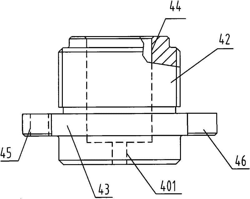
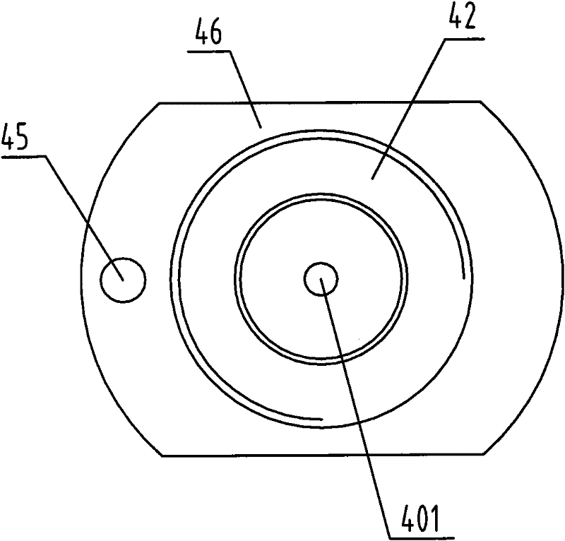
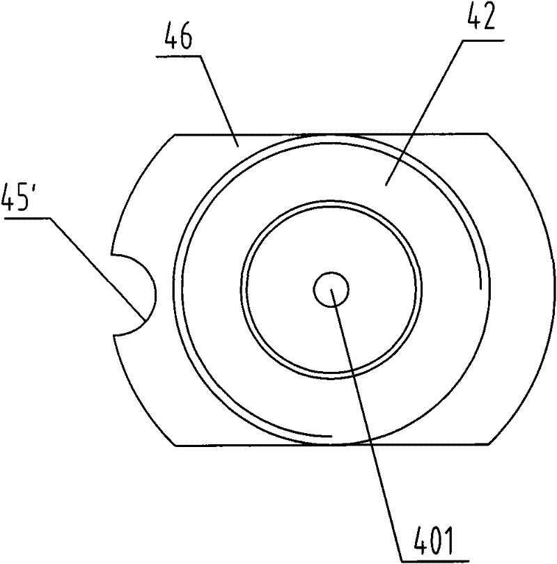
[0038] figure 2 It is a structural schematic diagram of Embodiment 2 of the spring end cap of the present invention. In order to better ensure the smoothness of the inner chamber of the pressure limiting device housing and the atmosphere, more effectively regulate the exhaust back pressure of the engine and dissipate heat in time, the first vent hole 401 can be opened as described in the first embodiment above. The quantity is one, and the opening position is at the center of the end face of the top cover. Such as figure 2 As shown, there may be a plurality of first vent holes 401 as required, which are opened symmetrically on the end surface of the top cover 43 .

[0039] Other features of this embodiment are the same as those of Embodiment 1, refer to Embodiment 1, and will not be repeated here.

Embodiment 3

[0041] image 3 It is a structural schematic diagram of Embodiment 3 of the spring end cap of the present invention. Such as image 3As shown, as a more preferred solution, on the basis of the first embodiment, a second air hole 402 is opened on the end surface of the top cover 43 , which is opened symmetrically around the periphery of the first air hole 401 .

[0042] Other features of this embodiment are the same as those of Embodiment 1, refer to Embodiment 1, and will not be repeated here.

[0043] Spring end cover embodiment four

[0044] Figure 4 It is a structural schematic diagram of Embodiment 4 of the spring end cap of the present invention. On the basis of the second embodiment, according to the requirements of the number of springs in the pressure limiting device, the inner cavity 44 of the spring end cover can be set as a stepped shape in addition to being set as a blind hole. Such as Figure 4 As shown, the inner cavity 44 of the top cover 43 is a stepped ...


PUM


Abstract

The invention provides a spring end cover of an exhausting brake butterfly valve. The spring end cover consists of a sleeve (42) and a top cover (43); an inner cavity (44) for accommodating a pressure limitation spring (7) is formed inside the spring end cover; a screw thread is formed on the outer circle of the sleeve (42); a first ventilating hole (401) is formed on the end face of the top cover (43); and the first ventilating hole (401) is communicated with the inner cavity (44). The invention also provides an exhausting brake butterfly valve with the spring end cover. By the invention, unobstructed communicating between the inner cavity of a shell of the pressure limitation device in the exhausting brake butterfly valve and the atmosphere is guaranteed; an air resistance is zero during reciprocating motion of a pressure limitation sealed piston; and exhausting back pressure of an engine can be regulated and controlled effectively and heat can be dissipated immediately, so that failure of the pressure limitation spring due to high temperature can be prevented.

Description

technical field [0001] The invention relates to a spring end cover of an exhaust braking butterfly valve and the exhaust braking butterfly valve, belonging to the technical field of mechanical manufacturing. Background technique [0002] Exhaust brake is an auxiliary braking device for vehicles, especially suitable for (heavy) trucks, large passenger cars and engineering vehicles, which can enhance the braking performance of vehicles without using or using less main brakes (traditional friction brakes) , can control the vehicle within a certain safe speed range, prevent vehicle brake failure, and ensure driving safety. [0003] The existing exhaust brake mainly consists of a cylinder or a vacuum booster cylinder and an exhaust brake valve connected thereto. When the vehicle is running normally, the exhaust gas from the engine flows through the exhaust brake valve and then is discharged. When braking is required, the vehicle's control system controls the movement of the cyl...

Claims


Application Information

Patent Timeline
Patent Type & Authority Applications(China)
IPC IPC(8): F02D9/10F02D9/06
Inventor 吴科峰
Owner ZHEJIANG EASUN PNEUMATIC SCI & TECH
Why Eureka
Try Eureka