Blower impeller

A technology of blower blades and blades, which is applied in the field of blowers, can solve problems such as poor heat dissipation performance of blowers, inability to cool the motor, and serious heating of the motor, etc., and achieve the effects of facilitating heat dissipation, increasing service life, and reducing temperature

Inactive Publication Date: 2013-09-25
开平市永强风机制造有限公司
View PDF6 Cites 5 Cited by
  • Summary
  • Abstract
  • Description
  • Claims
  • Application Information

AI Technical Summary

Problems solved by technology

However, there is generally no opening on the center plate. When the blower impeller rotates, the motor at the rear of the blower will heat up more seriously, and the wind entering from the front of

Method used


Image

  • Blower impeller

Examples


Example Embodiment

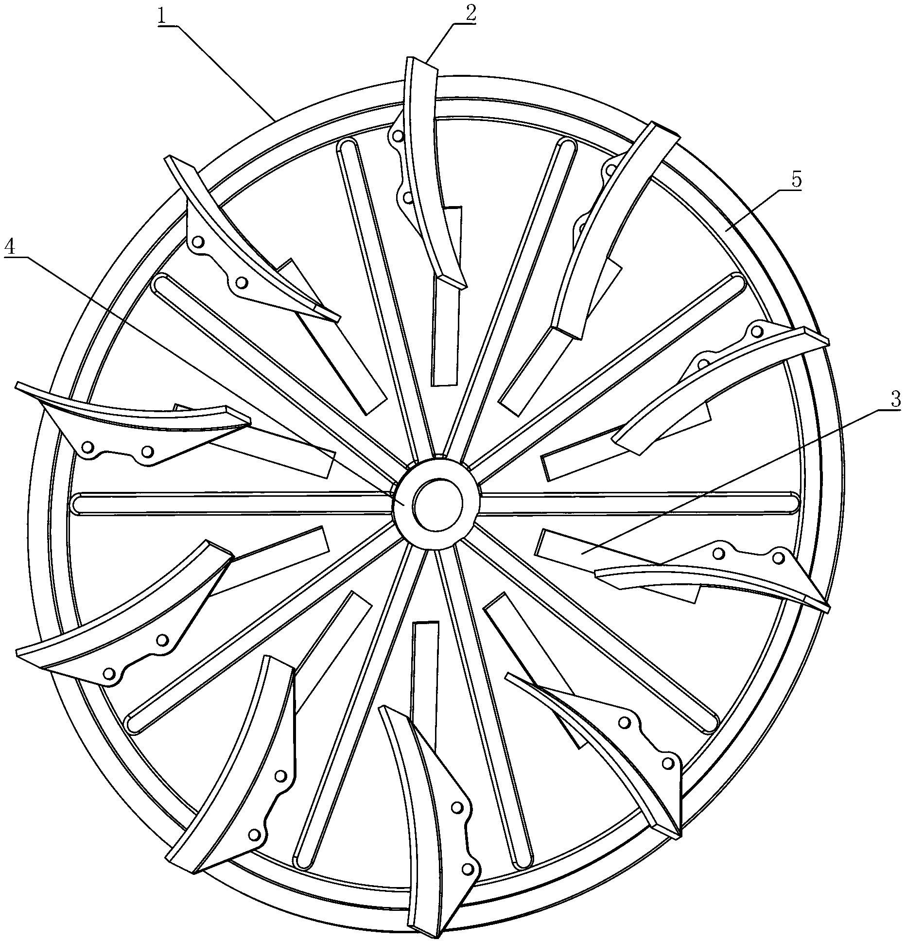
[0011] Such as figure 1 As shown, a blower impeller includes a center disk 1 and blades 2 fixedly connected to the center disk 1. The blades 2 are evenly distributed along the circumferential direction of the center disk 1, and the center disk 1 is provided with a plurality of squares. The openings 3 are evenly distributed along the circumferential direction of the central disk 1. As a preference of the present invention, the central part of the center plate 1 is stamped and formed with a recess 4 for easy installation of bolts or gaskets. Preferably, an annular groove 5 is formed by stamping and forming of the center disk 1 close to its edge. The center plate 1 of the present invention is provided with a plurality of square holes 3, and the wind entering from the front of the blower can be blown to the motor from the square holes 3 to cool the motor, reduce the temperature of the motor, and benefit the motor Heat dissipation can effectively increase the service life of the m...


PUM


Abstract

The invention discloses a blower impeller comprising a central disc and blades fixedly connected to the central disc. The blades are peripherally and evenly distributed on the central disc. The central disc is provided with a plurality of square openings evenly distributed on the periphery of the central disc. The square holes in the central disc allow air entering from the front of a blower to blow to a motor from the square holes so as to cool the motor, so that motor temperature can be reduced, the motor can be cooled and the service life of the motor is effectively prolonged.

Description

technical field [0001] The invention relates to a blower, in particular to a blower impeller. Background technique [0002] At present, the impeller on the blower generally includes a central disk and blades fixed on the central disk, and the blades are evenly distributed along the circumference of the central disk. However, there is generally no opening on the center plate. When the blower impeller rotates, the motor at the rear of the blower will heat up more seriously, and the wind entering from the front of the blower will directly go out from the air duct provided on the blower casing, which will not affect the motor. To the cooling effect, so the heat dissipation performance of the blower is not good. Contents of the invention [0003] In order to overcome the deficiencies in the prior art, the invention provides an impeller that allows the wind energy that enters from the front of the blower to cool the motor of the blower. [0004] The technical solution adopted ...

Claims


Application Information

Patent Timeline
IPC IPC(8): F04D29/30F04D29/58
Inventor 谭颖雅
Owner 开平市永强风机制造有限公司
Why Eureka
Try Eureka