LED (Light Emitting Diode) down lamp

A technology for LED downlights and radiators, which is applied to lighting devices, cooling/heating devices of lighting devices, light sources, etc., can solve the problems of high production cost, inconvenient installation and maintenance, affecting the service life of LED lights, etc. Easy to combine and maintain, prolong service life, good heat dissipation effect

Inactive Publication Date: 2013-09-25
KINGSUN OPTOELECTRONIC CO LTD
View PDF5 Cites 2 Cited by
  • Summary
  • Abstract
  • Description
  • Claims
  • Application Information

AI Technical Summary

Problems solved by technology

The structure of the existing LED downlight lamp holder is relatively complex, usually composed of multiple parts, and the parts are fixed with screws, resulting in many production processes for LED lights, high production costs, inconvenient installation and maintenance, and after repeated maintenance Prone to problems such as screw stripping
[0003] In addition, LED chips will generate a lot of heat when they work. If the heat dissipation performance of the device is poor, the heat will not be dissipated quickly, which will affect its performance and use. Life-span effects can even be fatal
As far as the current situation is concerned, the heat dissipation structure of LED downlights is generally more complicated, and the heat dissipation effect is not ideal. If the heat dissipation cannot be effective, the service life of LED lights will be affected

Method used


Image

  • LED (Light Emitting Diode) down lamp
  • LED (Light Emitting Diode) down lamp
  • LED (Light Emitting Diode) down lamp

Examples


Embodiment Construction

[0036] In order to facilitate the understanding of those skilled in the art, the present invention will be further described below in conjunction with the embodiments and accompanying drawings, and the contents mentioned in the embodiments are not intended to limit the present invention. see Figure 1 to Figure 6 , the present invention will be described in detail below in conjunction with the accompanying drawings.

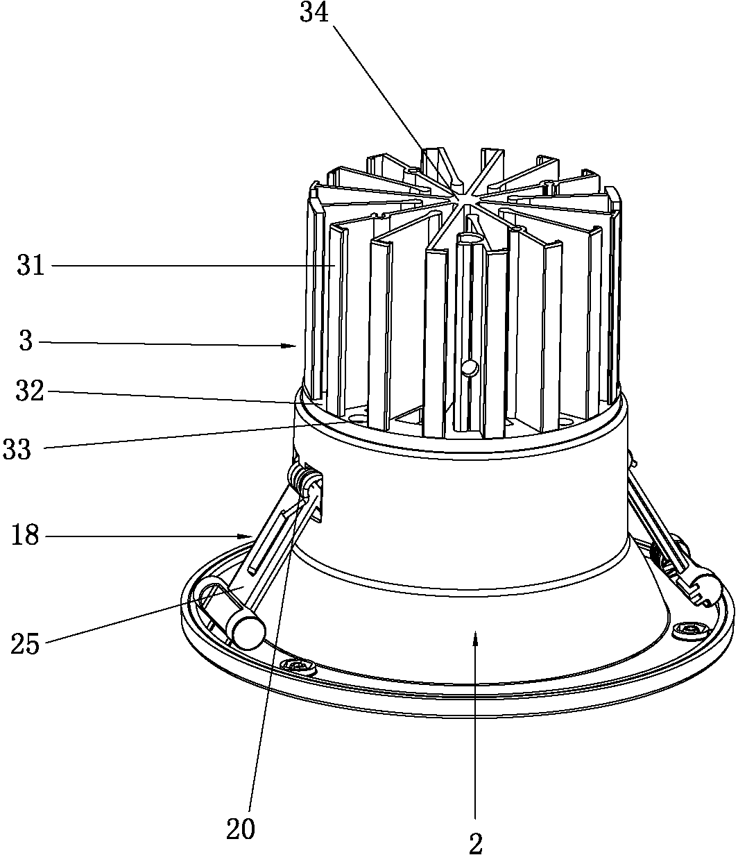
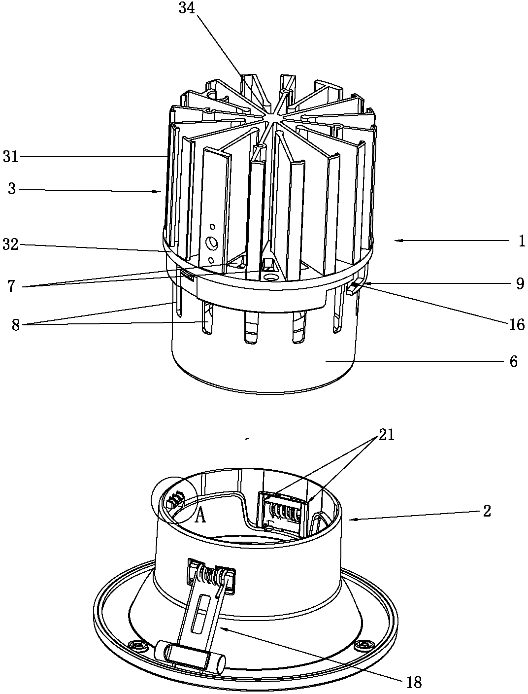
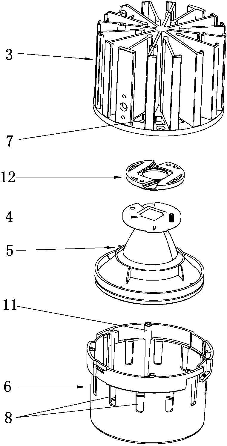
[0037] An LED downlight in this embodiment includes a light engine module 1 and a cover body 2, the light engine module 1 includes a radiator 3, a light source 4, a reflector 5 and a housing 6, and the radiator 3 and the housing 6 The upper end of the light source 4 is connected, the reflector 5 is connected with the lower end of the light source 4, and the light source 4 and the reflector 5 are installed in the inner cavity of the housing 6, and the upper end of the housing 6 is fixedly connected with the radiator 3, so The heat sink 3 is provided with a heat d...


PUM


Abstract

The invention relates to the technical field of illumination lamps, particularly to an LED (Light Emitting Diode) down lamp. The LED down lamp comprises an optical engine module and a cover body; the optical engine module comprises an radiator, a light source, a reflecting cover and a casing; the radiator is provided with heat dissipation through holes which are communicated with a casing inner chamber; a plurality of through holes are formed in the casing. When the LED down lamp is used, gas inside and outside the casing generates convection due to the fact that intensity of pressure inside and outside the casing is different, a part of heat is directly emitted out through the through holes and the heat dissipation through holes, and another part of heat is emitted out through the radiator, so that the LED down lamp is good in heat dissipation effect and the service life of the down lamp is prolonged. A fastening strip is fixedly arranged at external side of the casing and a fastening groove which is matched with the fastening strip is formed at the internal side of the cover body, so that the LED down lamp can be fixedly assembled by correspondingly rotating the fastening strip and the fastening groove, close assembling can be achieved without using special tools, and accordingly the LED down lamp is simple in structure and convenient to install, assemble and maintain.

Description

technical field [0001] The invention relates to the technical field of lighting fixtures, in particular to an LED downlight. Background technique [0002] With the development of LED technology and the advantages of energy saving, long life and low radiation, LED lights are more and more widely used. Although LED lights have many advantages, there are also many disadvantages. The structure of the existing LED downlight lamp holder is relatively complex, usually composed of multiple parts, and the parts are fixed with screws, resulting in many production processes for LED lights, high production costs, inconvenient installation and maintenance, and after repeated maintenance Problems such as screw tripping are prone to occur. [0003] In addition, LED chips will generate a lot of heat during operation. If the heat dissipation performance of the device is poor, the heat will not be dissipated quickly, and the impact on its performance and service life will even be fatal. As...

Claims


Application Information

Patent Timeline
Patent Type & Authority Applications(China)
IPC IPC(8): F21S2/00F21V29/00F21V17/10F21V17/16F21Y101/02F21V29/50F21V29/83
Inventor 宗金华何新广
Owner KINGSUN OPTOELECTRONIC CO LTD
Why Eureka
Try Eureka