Comprehensive monitoring device of overhead line

An overhead line, comprehensive monitoring technology, used in measuring devices, indicating the existence of current/voltage, instruments, etc., can solve the problems of unstable working power supply, inconvenient maintenance work, short circuit of lines, etc., to improve work efficiency and economic efficiency, The effect of reducing safety hazards and labor intensity

Active Publication Date: 2013-09-25
ZHUHAI COPOWER ELECTRIC
View PDF8 Cites 2 Cited by
  • Summary
  • Abstract
  • Description
  • Claims
  • Application Information

AI Technical Summary

Problems solved by technology

[0003] In the prior art, the functions of the power monitoring auxiliary equipment applied on the overhead line are very scarce and all adopt the form of internal power supply or external power supply for power supply. And maintenance work is comparatively inconvenient; In addition, the electric power monitoring auxiliary equipment in the prior art also has the defect on the following functions: 1, existing equipment does not possess the live line display function
2. Existing equipment does not have load current detection function
3. The existing equipment does not have the function of repelling birds. Birds build nests on elevated lines, and holding branches or iron wires in their mouths is likely to cause short circuits on the lines, and larger birds flying or fighting between wires may also cause short circuits between phases

Method used


Image

  • Comprehensive monitoring device of overhead line

Examples


Embodiment Construction

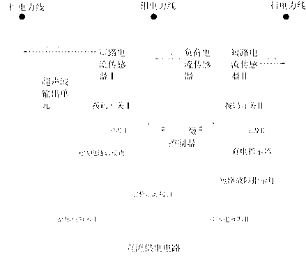
[0016] Such as figure 1 As shown, the present invention is used for the comprehensive monitoring of A, B, C three-phase overhead line status, and it comprises the MCU microcontroller 1 that is equipotentially connected with the B-phase power line, the load current sensor 2 that is electromagnetically induced with the B-phase power line and The short-circuit current sensor I3 and the short-circuit current sensor II4 that are electromagnetically induced to the A-phase power line and the C-phase power line respectively, the load current sensor 2 is electrically connected to the MCU microcontroller 1; the short-circuit current sensor I3 and the short-circuit current The sensor II4 is electrically connected to the LED light source I31 and the LED light source II41 respectively, the dial switch I8 is electrically connected between the short-circuit current sensor I3 and the LED light source I31, and the short-circuit current sensor II4 is connected to the LED light source II41. Elec...


PUM


Abstract

The invention discloses a comprehensive monitoring device of an overhead line. The comprehensive monitoring device of the overhead line takes electricity through the high voltage and integrates the functions of circuit live display, short-circuit fault indication, load current detection, and ultrasonic bird repelling. The comprehensive monitoring device of the overhead line comprises a micro controller unit which is connected with a B-phase power line, a load current sensor, a short-circuit current sensor I and a short-circuit current sensor II, wherein electro-magnetic induction exists between the load current sensor and the B-phase power line, electro-magnetic induction exists between an A-phase power line and the short-circuit current sensor I, electro-magnetic induction exists between a C-phase power line and the short-circuit current sensor II, the load current sensor is electrically connected with the MCU, the short-circuit current sensor I is electrically connected with an LED light source I, the short-circuit current sensor II is electrically connected with an LED light source II, and the LED light source I and the LED light source II are in optical coupling with the MCU. The comprehensive monitoring device of the overhead line further comprises a high-voltage capacitor I which is electrically connected with the A-phase power line, a high-voltage capacitor II which is electrically connected with the C-phase power line, and a direct-current power supply circuit which is electrically connected with the high-voltage capacitor I and the high-voltage capacitor II, wherein the direct-current power supply circuit is electrically connected with the MCU.

Description

technical field [0001] The invention relates to an overhead line comprehensive monitoring device applied in the field of electric power system. Background technique [0002] The 10kV line is an important part of the power system, which is responsible for the important task of transmitting and distributing electric energy; as we all know, the 10kV line is directly connected to thousands of households through transformers, so the monitoring of the operating status of the 10kV line and the monitoring of the 10kV line Maintenance and overhaul are very important. Since the 10kV line has the characteristics of "multiple lines, multiple points, and wide area", and there are many branch switches installed on the line, it is troublesome and dangerous to inspect, maintain and overhaul the 10kV line. [0003] In the prior art, the functions of the power monitoring auxiliary equipment applied on the overhead line are very scarce and all adopt the form of internal power supply or extern...

Claims


Application Information

Patent Timeline
IPC IPC(8): G01R19/00G01R19/145G01R31/02
Inventor 周迭辉段传宗陈宪庭
Owner ZHUHAI COPOWER ELECTRIC
Why Eureka
Try Eureka