Eureka AIR delivers breakthrough ideas for toughest innovation challenges, trusted by R&D personnel around the world.

Image forming apparatus and method of controlling the same

An image and control part technology, which is applied in the direction of electric recording process applying charge pattern, equipment of electric recording process applying charge pattern, electric recording technique, etc. Effect

Active Publication Date: 2013-09-25
KONICA MINOLTA BUSINESS TECH INC
View PDF5 Cites 4 Cited by
  • Summary
  • Abstract
  • Description
  • Claims
  • Application Information

AI Technical Summary

Problems solved by technology

[0004] However, in the prior art as described above, there is a problem that the structure of the device becomes complicated or the size of the device is increased due to the installation of the recovery member or the suction member as described above.

Method used


Image

  • Image forming apparatus and method of controlling the same
  • Image forming apparatus and method of controlling the same
  • Image forming apparatus and method of controlling the same

Examples


Deformed example (1

[0068] The printer 10 of the modification (1) may have the same configuration as the above-mentioned printer 10 except for the parts described below. Next, differences between the printer 10 of the modified example (1) and the printer 10 described above will be described.

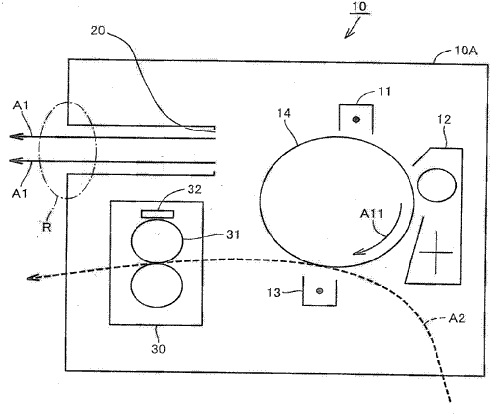
[0069] in reference to Figure 5 In the opening and closing control of the shutter 21 described above, the shutter 21 is closed when the surface temperature of the fixing roller 31 exceeds 170° C., and the shutter 21 is opened when the temperature of the surface of the fixing roller 31 is 170° C. or lower. In this case, it is conceivable that when the surface temperature of the fixing roller 31 slightly fluctuates around 170° C., the opening and closing states of the shutters 21 are frequently switched.

[0070]In order to avoid such a situation, in the opening and closing control of the louver 21, the louver 21 may be closed when the surface temperature of the fixing roller 31 exceeds a first temperature,...

Deformed example (2

[0073] The printer 10 of the modification (2) may have the same configuration as the above-mentioned printer 10 except for the parts described below. Next, differences between the printer 10 of the modification (2) and the printer 10 described above will be described.

[0074] In the printer 10, when the temperature of the fixing roller 31 rises, the air outlet 20 is closed. In order to suppress the temperature rise in the casing 10A caused by such control, the printer 10 may further include a fan different from the fan 160 .

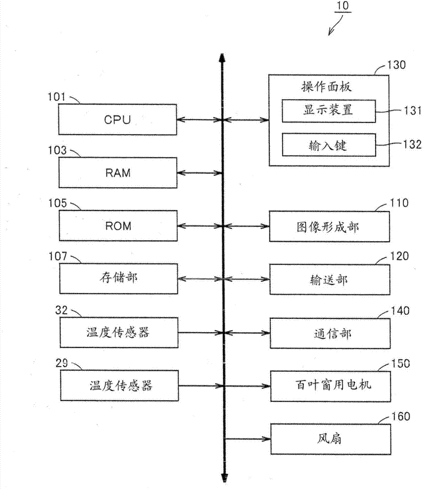
[0075] Figure 7 It is a figure for demonstrating the cooling method of the housing|casing 10A by the fan different from the fan 160. Figure 8 It is a diagram showing the hardware configuration of the printer 10 according to the modification (2).

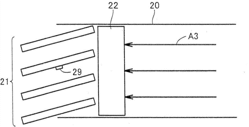
[0076] refer to Figure 7 , in the modified example (2), the external fan 23 provided separately cools the louver 21 provided in the exhaust port 20 from the outside of the housing 10A. When the louver ...

Deformed example (3

[0079] The printer 10 of the modification (3) may have the same configuration as the above-mentioned printer 10 except for the parts described below. Next, differences between the printer 10 of the modification (3) and the printer 10 described above will be described.

[0080] In modification (3), in the opening and closing control of the louver 21 , when a specific condition is satisfied, the louver 21 is opened even if the surface temperature of the fixing roller 31 exceeds 170° C.

[0081] The specific condition in the modified example (3) is that the temperature near the air outlet 20 (hereinafter also referred to as the temperature near the opening of the housing 10A) exceeds a specific temperature. That is, in the modified example (3), when the temperature near the exhaust port 20 exceeds a specific temperature, even if the surface temperature of the fixing roller 31 exceeds 170° C., the louver 21 is opened.

[0082] Figure 9 It is a flowchart of the opening and closi...


PUM


Abstract

An image forming apparatus (10) has an outline surrounded by a casing (10A). The casing has an opening (20). The image forming apparatus includes a fixing unit (30) configured to fix an image formed on a recording medium, and a control unit. The fixing unit includes a heating fixing member (31). The control unit is configured to control an opening degree of the opening based on temperature of a surface of or in the vicinity of the heating fixing member, so as to prevent emission of a substance by an air current to outside of the casing through the opening, during an image forming operation.

Description

technical field [0001] The present invention relates to an image forming apparatus and a control method thereof, and more particularly to an image forming apparatus including a fixing unit for fixing a toner image on a recording medium and a control method thereof. Background technique [0002] In electrophotographic image forming apparatuses, various techniques for preventing ozone, toner dust, and the like generated in the apparatus from flowing out of the apparatus have been studied. [0003] In recent years, it has been found that not only ozone and toner dust but also ultrafine particles with a particle diameter of 100 nm or less (hereinafter also appropriately referred to as "UFP" (Ultra Fine Particle)) are generated in such image forming apparatuses. . Furthermore, a technique for suppressing the outflow of UFP to the outside of the device has been proposed, for example, in (Japanese) Unexamined Patent Application Publication No. 2010-002803. In this document, the i...

Claims


Application Information

Patent Timeline
Patent Type & Authority Applications(China)
IPC IPC(8): G03G15/20G03G15/00
CPCG03G21/206G03G21/20
Inventor 堀江贵之林英明齐藤正志羽田野英纪森田修米田哲
Owner KONICA MINOLTA BUSINESS TECH INC
Why Eureka
Eureka Blog
Learn More