

Infrared-reflecting substrate
An infrared and substrate technology, applied in the direction of reflection/signal coatings, coatings, instruments, etc., can solve the problem of low transparency and achieve the effects of high transparency, excellent infrared reflection performance, and simple manufacturing
- Summary
- Abstract
- Description
- Claims
- Application Information
AI Technical Summary
Problems solved by technology
Method used
Image

Examples
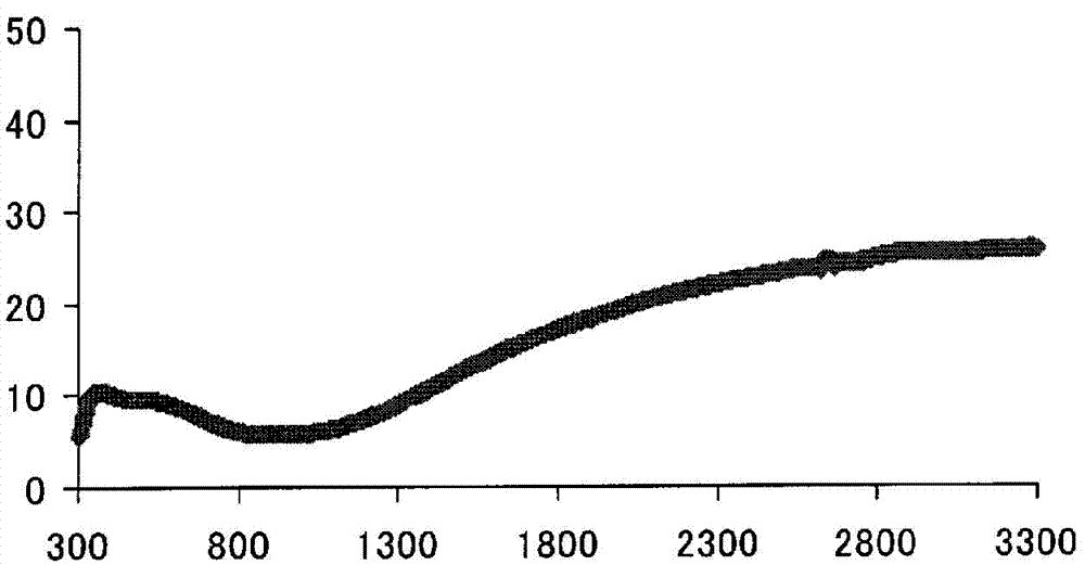
Embodiment 1)
[0093] (Example 1) Example of using plate glass:
[0094] 50.0 g of an aqueous dispersion of a composite of poly(3,4-ethylenedioxythiophene) and polystyrenesulfonic acid (manufactured by Heraeus Co., Ltd.: CleviosP, conductivity 0.09 S / cm, solid content 1.3%), 0.5 g of surfactant (solids 10%), 0.05 g of leveling agent (solids 100%), 2 g of water, and 8 g of ethanol were mixed and stirred for 30 minutes. The resulting mixture was filtered through a 400-mesh SUS-made sieve to prepare a coating agent.
[0095] The obtained coating agent was coated on a blue plate glass (manufactured by advanced materials technology Co., Ltd.: AMT-8292) with a thickness of 0.7 mm by the bar coating method using a wire bar No. 8 (wet film thickness 18 μm), and Dry at 100° C. for 1 minute to obtain a base.
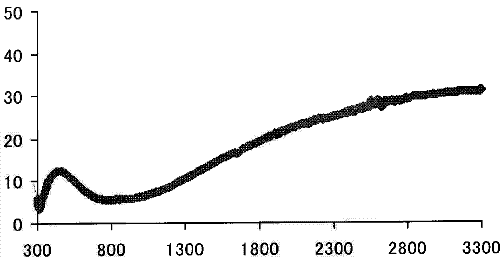
Embodiment 2)
[0096] (Example 2) Example of using plate glass:
[0097] Instead of CleviosP in Example 1, Clevios P HC V4 (manufactured by Heraeus Co., Ltd.: conductivity 0.23 S / cm, solid content 1.2%), the matrix was obtained by the same method as in Example 1.
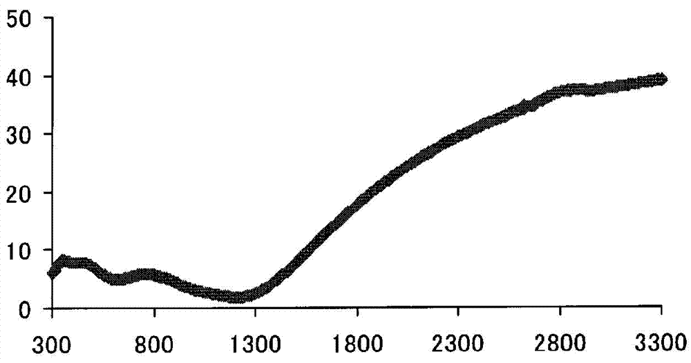
Embodiment 3)
[0098] (Example 3) Example of using plate glass:
[0099] Instead of CleviosP in Example 1, Clevios PH1000 (manufactured by Heraeus Co., Ltd.: conductivity 0.46 S / cm, solid content 1.1%), the matrix was obtained by the same method as in Example 1.
PUM
| Property | Measurement | Unit |
|---|---|---|
| thickness | aaaaa | aaaaa |
| electrical conductivity | aaaaa | aaaaa |
| reflectance | aaaaa | aaaaa |
Abstract
Description
Claims
Application Information