Hanging cage walls and hanging cages

A technology of hanging cages and surrounding walls, which is applied to elevators, transportation and packaging in buildings, etc. It can solve the problems of short service life of surrounding walls, achieve the effects of improving service life, firm design and reducing manufacturing costs

Inactive Publication Date: 2015-09-23
嘉兴市华东建设机械有限公司
View PDF10 Cites 0 Cited by
  • Summary
  • Abstract
  • Description
  • Claims
  • Application Information

AI Technical Summary

Problems solved by technology

[0004] The enclosure wall of the hanging cage and the hanging cage provided by the present invention aim to overcome the short service life of the enclosure wall in the prior art

Method used


Image

  • Hanging cage walls and hanging cages
  • Hanging cage walls and hanging cages
  • Hanging cage walls and hanging cages

Examples


Embodiment 1

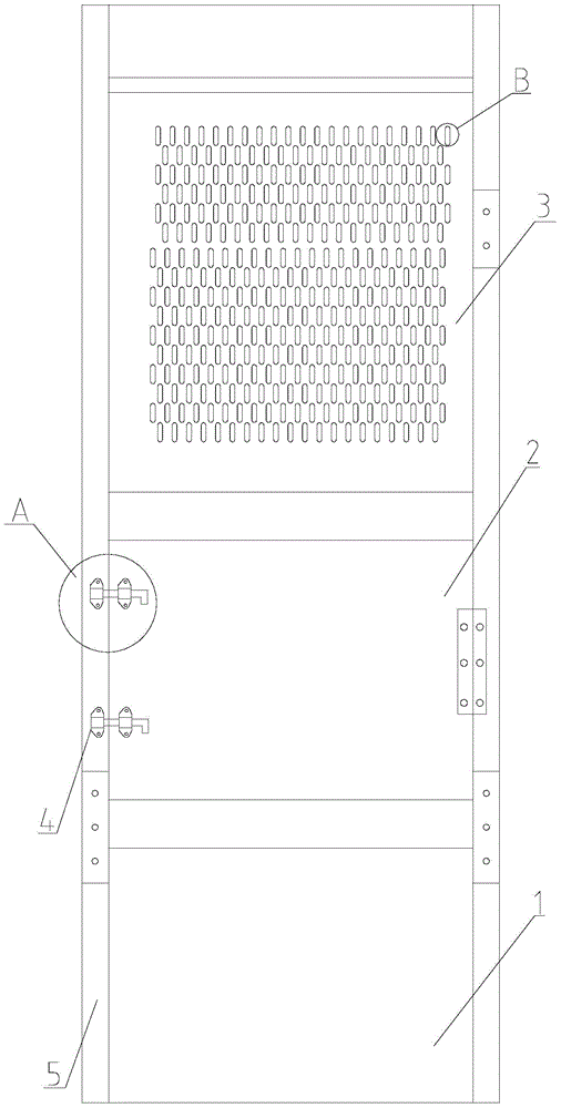
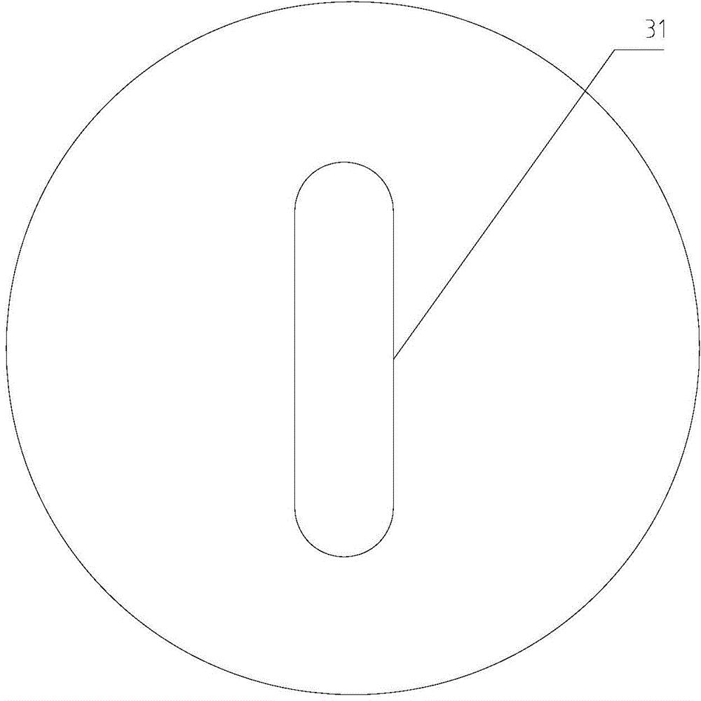
[0022] Below in conjunction with accompanying drawing, the hanging cage surrounding wall of the present invention will be further described. Such as figure 1 , image 3 As shown, the surrounding wall of the hanging cage, the surrounding wall includes the anti-skid plate 1 welded on the lower part of the side wall of the hanging cage 5, the closing plate 2 arranged in the middle part of the side wall of the hanging cage 5, and the cross-sectional shape of the through hole 31 is rectangular and bolted The punching plate 3 fixed on the upper part of the side wall of the hanging cage 5, the height of the surrounding wall anti-skid plate 1 accounts for 1 / 3 to 1 / 2 of the total height of the hanging cage 5 is arranged on the lower part of the side wall of the hanging cage 5, and the surrounding wall The height of the closing plate 2 accounts for 1 / 4-1 / 3 of the height of the cage 5 and is arranged in the middle of the cage 5. The rest of the surrounding wall is a punching plate 3. Th...

Embodiment 2

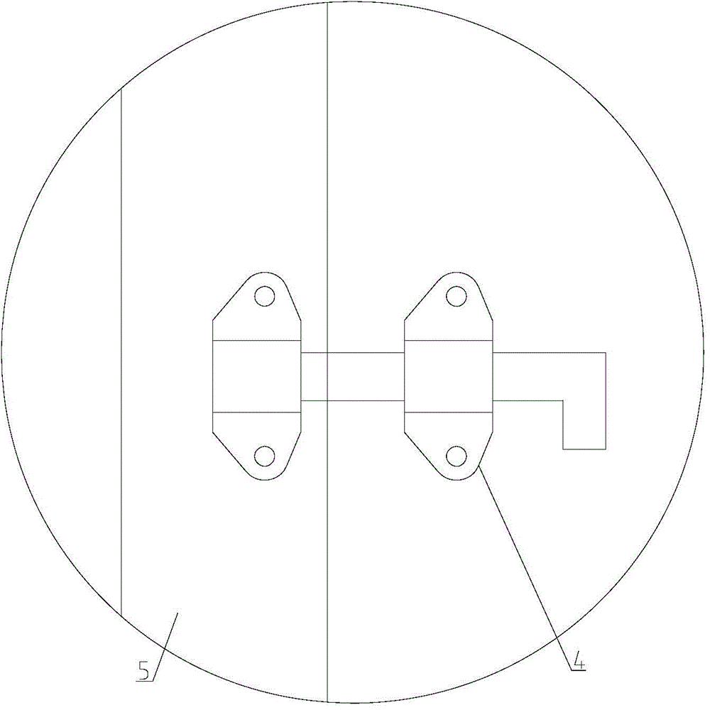
[0027] The difference between this embodiment and Embodiment 1 is that, as figure 1 , figure 2As shown, one end of the closing plate 2 on one side of the surrounding wall close to the guide rail of the cage is connected to the cage 5 in rotation and the other end is fixed on the cage 5 through a locking device 4. One end of the closing plate 2 can be hinged, The connecting means such as pin shafts are rotatably connected on the cage 5, and two locking devices 4 are arranged between the cage 5 and the closing plate 2, and the locking devices 4 include a latch and a setting In the slot on the hanging cage 5, the locking device 4 is opened during the operation, and the other end of the closing plate 2 is arranged on the hanging cage 5 through a rotating connection. The opening operation of the closing plate 2 is very convenient, and the closing plate 2 is closed after the maintenance is completed The assembly operation is also very convenient. It only needs to lock the locking ...


PUM


Abstract

The invention relates to the field of building machines, in particular to a cage enclosure and a cage. The cage enclosure comprises an anti-sliding plate, a closing plate and a punching plate, wherein the anti-sliding plate, the closing plate and the punching plate are arranged on the side wall of the cage from top to down. Due to the fact that the anti-sliding plate is arranged in the bottom portion of the enclosure, the strength of the enclosure is guaranteed and impact and damage to the enclosure are prevented during the process of loading goods. The closing plate is arranged in the middle portion of the enclosure, the middle portion of the enclosure is not easy to impact and collide, and therefore manufacturing cost of the enclosure is lowered by the adoption of the enclosing plate. Due to the fact that the punching plate is arranged on the upper portion of the enclosure, light transmittance performance and ventilation performance of the cage are improved, and operators work comfortably. The enclosure is firm, attractive and comfortable in overall design and convenient to manufacture, and the service life of the enclosure is prolonged. According to the cage, the enclosure arranged in the cage, the design completely meets the requirement of the standard of GB26557-2011 GB26557-2011'cage with vertically-guiding construction lift for carrying people and goods' and the service life of the cage is prolonged.

Description

technical field [0001] The invention relates to the field of construction machinery, in particular to surrounding walls of a hanging cage and a hanging cage. Background technique [0002] The elevator is an indispensable mechanical equipment in the construction process of modern high-rise buildings. Its main function is to transport the building materials on the ground to the high-rise construction site. The transportation efficiency of the elevator directly affects the progress of the project, especially the cage of the elevator. The main transportation structure of the elevator is responsible for the transportation of materials. For this reason, the country has made various standards for the elevator, so that the elevator can meet the requirements of construction safety while ensuring efficiency. Due to the relatively harsh working environment of the elevator, in When designing the structure of the cage, it is necessary to set up a surrounding wall on the inner or outer wa...

Claims


Application Information

Patent Timeline
Patent Type & Authority Patents(China)
IPC IPC(8): B66B11/02
Inventor 姚文中唐全法杨正明刘源
Owner 嘉兴市华东建设机械有限公司
Why Eureka
Try Eureka