
Three-nozzle offset inclination angle induced air smoke evacuator

A technology of induced draft, exhaust, and offset, applied in waste heat treatment, furnace, lighting and heating equipment, etc., can solve the problems of unstable kiln pressure, failure of impeller dynamic balance, corrosion of bearing bush of fan, etc., to overcome turbulent flow resistance. Hysteresis, solving dynamic balance failure, low consumption and energy saving effect of smoke exhaust

Inactive Publication Date: 2013-10-02
重庆正川医药包装材料股份有限公司 +1
View PDF0 Cites 0 Cited by
  • Summary
  • Abstract
  • Description
  • Claims
  • Application Information

AI Technical Summary

Problems solved by technology

Since the flue gas induced draft fan is in direct contact with the kiln exhaust gas, the impeller of the induced draft fan needs to be cleaned within 2-3 days. With the thickening of the residual adhesive on the impeller, the cleaning effect is very poor, and the dynamic balance failure of the impeller often occurs Symptoms, and the bearing bushes of the fan are also severely corroded, resulting in unstable kiln pressure and affecting the normal production of the kiln
The second is to use a jet fan to induce air and smoke exhaust device, and use a high-pressure fan to inject air to induce air. Although it avoids the direct contact between the fan impeller and the motor and the flue gas discharged from the kiln, because the injection head is arranged at the center of the flue outlet and Parallel to the flue, so an aerodynamic turbulent zone is formed in the middle and lower part of the flue, resulting in a blocking effect. The higher the wind speed, the more obvious the blocking effect, just like the bigger the faucet is opened, the higher the splash, sometimes even The kiln pressure is unstable, which affects the normal operation of the kiln
Existing smoke exhaust technology has serious defects in efficiency and energy saving

Method used


Image

  • Three-nozzle offset inclination angle induced air smoke evacuator

Examples


Embodiment Construction

[0008] Combine below figure 1 The implementation of the present invention will be described.

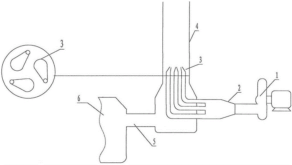
[0009] figure 1 Among them, the end outlet of the air outlet pipe (2) connected to the fan (1) is connected with three offset angle spray heads (3), and the three offset angle injection heads (3) are installed near the side of the flue (4) , the flue (4) is connected to the flue and the kiln tail gas inlet (5), and the tail gas inlet (5) is next to the kiln (6).

[0010] The blower (1) injects high-pressure air into the jet flue (4) through three offset nozzles (3) to create a negative pressure, and the three high-speed air flows engulf the flue gas in the flue (4) to form a spiral air flow In this way, the aerodynamic turbulent zone formed in the middle and lower part of the flue (4) is basically eliminated, and the problem of stagnation is solved, and the flue gas in the kiln (6) is quickly discharged. This not only meets the non-contact requirements, but also overcomes the aero...


PUM


Abstract

The invention relates to a three-nozzle offset inclination angle induced air smoke evacuator, which consists of a fan, an air outlet pipe, three offset inclination angle jetting heads, a flue and a kiln tail gas inlet, wherein the three jetting heads are positioned in a way of forming included angles of 120 degrees with one another, incline at obtuse angles relative to a horizontal plane, and are positioned close to the side of the flue. Pressurized air is obliquely jetted and induced into the flue at a high speed by using the high-pressure fan via the three offset jetting heads to form a negative pressure, and three branches of high-speed air flow are mixed with flue gas in the flue to form spiral rising air flow, so that the blocking effect of a pneumatic turbulent area formed on the lower-middle part of the flue is eliminated basically, non-contact smoke evacuation is realized, a rapid, efficient, low-consumption and energy-saving smoke evacuation effect is achieved, and stable running of a kiln is ensured.

Description

technical field [0001] The invention relates to a jet fan induced air smoke exhaust device, especially through the eccentricity and inclination of the three nozzles, it can not only realize the non-contact active smoke exhaust of the kiln flue gas, but also solve the problem of rusting of the fan impeller due to residual adhesives. However, the symptoms of dynamic balance failure and serious corrosion of fan bearing bushes appear, and the turbulent flow blocking effect of the airflow in the middle and lower parts of the flue is well overcome, achieving a fast, efficient, low-consumption and energy-saving smoke exhaust effect. Background technique [0002] The currently prevailing kiln flue gas emission methods are as follows: one is to generally use a flue gas induced draft fan to directly place the flue gas at the outlet to draw it into the chimney for discharge. Since the flue gas induced draft fan is in direct contact with the kiln exhaust gas, the impeller of the induced...

Claims


Application Information

Patent Timeline
Patent Type & Authority Applications(China)
IPC IPC(8): F27D17/00
Inventor 毛世理范勇何良智向鲲
Owner 重庆正川医药包装材料股份有限公司
Learn More