
Optical cable tracer, optical cable and optical cable tracking method

A tracker and optical cable technology, applied in the field of optical communication, can solve the problems of troublesome maintenance, irresponsible maintenance, lack of maintenance, etc., and achieve the effect of convenient processing

Active Publication Date: 2013-10-02
SHENZHEN SDGI OPTICAL NETWORK TECH
View PDF6 Cites 3 Cited by
  • Summary
  • Abstract
  • Description
  • Claims
  • Application Information

AI Technical Summary

Problems solved by technology

[0003] For example: when the optical fiber active connector is being constructed in the computer room, the construction department is responsible for the maintenance, not responsible for maintenance. When the maintenance department maintains, when a problem occurs at one end of the optical fiber active connector, it is difficult for the maintenance personnel to quickly find the optical fiber active connector at the other end. The best method is to confirm according to the identification on the optical fiber active connector, which is very time-consuming, especially in different areas such as different cabinets, different machine rooms, and different floors. The lack of effective communication between the construction personnel of the department and the maintenance personnel of the maintenance department, the difficulty of this work will increase again
[0004] In terms of outstanding problems in construction and maintenance, in order to solve the troubles of operators in maintenance, the present invention provides a fast-tracking optical fiber active connector, which provides convenience and speed for operators to quickly find problems during maintenance.

Method used


Image

  • Optical cable tracer, optical cable and optical cable tracking method
  • Optical cable tracer, optical cable and optical cable tracking method
  • Optical cable tracer, optical cable and optical cable tracking method

Examples


Embodiment Construction

[0024] The present invention will be further described below in conjunction with the accompanying drawings.

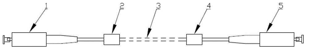
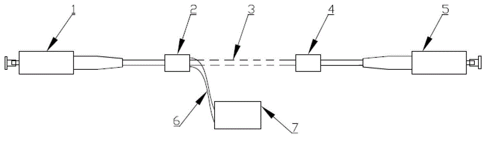
[0025] The principle of fast-tracking optical fiber active connector: on the basis of not changing the optical performance, mechanical performance, environmental performance, combustion performance, service life and other properties of the existing optical fiber active connector, the fast-tracking function of the optical fiber active connector is added , its tracking concept is to add light, sound, vibration, signal and other functions that attract people's attention to the connector of the optical fiber active connector to meet the tracking effect. When the problem is found, quickly and accurately locate the abnormal end of the optical fiber active connector.

[0026] Make a conventional connector on the optical cable, and add a tracker for tracking on the optical fiber active connector in a wired and wireless manner. Applicable to single-core optical cables, dual-co...


PUM


Abstract

The invention provides an optical cable tracer, an optical cable and an optical cable tracking method. The optical cable tracer comprises a first tracer and a second tracer, wherein the first tracer and the second tracer communicate with each other in a wired or wireless manner; the first tracer and the second tracer are provided with one or more items among a sound production component, a light-emitting component and a vibrating component; the optical cable comprises the optical cable tracer, the first tracer and the second tracer are arranged at two ends of the optical cable; the optical cable tracer and the optical cable are designed in an integrated or split manner. The optical cable tracking method is as follows: the first tracer and the second tracer are fixed at two ends of the optical cable respectively through the method of the integrated design or split design, and power is supplied for the first tracer or the second tracer. With adoption of the optical cable tracer, the optical cable and the optical cable tracking method, two ends of the optical cable can be rapidly found so as to deal with faulted optical cables conveniently, particularly under the condition that two ends of the optical cable are in different spaces.

Description

technical field [0001] The invention relates to the field of optical communication, in particular to an optical cable tracker and a tracking method. Background technique [0002] At present, with the rapid development of FTTH (FTTH (Fiber To The Home), as the name implies, a fiber directly to the home) in China, the annual investment of operators in computer rooms and cables is increasing at a rate of 30%, but the operation Operators have higher requirements in terms of product quality, cost, convenient construction, and quick maintenance. Facing the rapid growth of operator room construction, the pressure and investment in construction and maintenance are increasing, especially for operators. With a clear division of labor in management and a separate supervision model, more energy must be invested in the cost of later maintenance. [0003] For example: when the optical fiber active connector is being constructed in the computer room, the construction department is respons...

Claims


Application Information

Patent Timeline
IPC IPC(8): G02B6/38G02B6/44
Inventor 郭建民魏杰沙和鸣张启武郭兆程
Owner SHENZHEN SDGI OPTICAL NETWORK TECH
Features
  • Generate Ideas
  • Intellectual Property
  • Life Sciences
  • Materials
  • Tech Scout
  • Unparalleled Data Quality
  • Higher Quality Content
  • 60% Fewer Hallucinations
Learn More