A circuit portion of a semi-automatic wood children's bed trademark thermoprinting machine

A hot stamping machine, semi-automatic technology, applied in the sequence/logic controller program control, electrical program control and other directions, can solve the problems of inapplicable hot stamping trademarks, heating interrupt hot stamping temperature, etc., to achieve automatic control of hot stamping time Effect

Active Publication Date: 2013-10-02
SHUCHENG HONGYE HARDWARE & PLASTIC PROD
View PDF7 Cites 1 Cited by
  • Summary
  • Abstract
  • Description
  • Claims
  • Application Information

AI Technical Summary

Problems solved by technology

However, ordinary trademark stamping machines are not suitable for stamping trademarks on wooden products, and the circuit part of the wooden crib trademark stamping machine also needs to be individually designed according to the structure of the wooden crib trademark stamping machine to avoid hot During the printing process, the heating interruption caused by short circuit, etc. and the hot stamping temperature is too high or too low

Method used


Image

  • A circuit portion of a semi-automatic wood children's bed trademark thermoprinting machine
  • A circuit portion of a semi-automatic wood children's bed trademark thermoprinting machine

Examples


Embodiment Construction

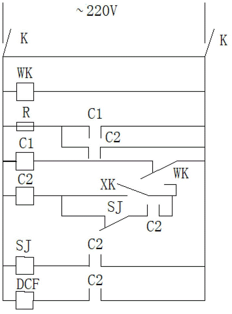
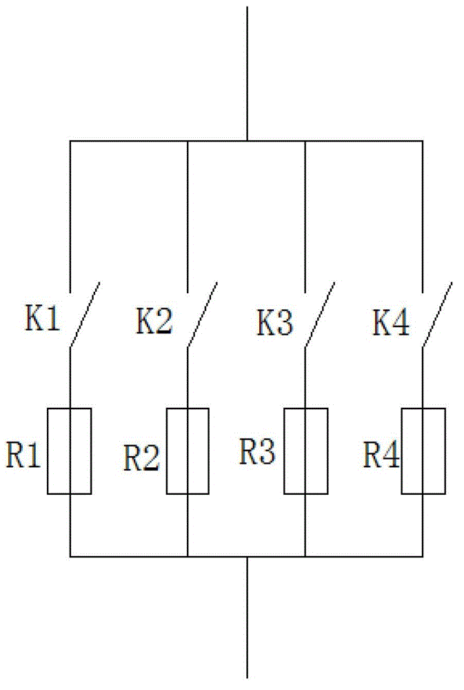
[0016] Such as figure 1 , 2 As shown, the circuit part of a semi-automatic wooden crib trademark hot stamping machine includes six branches connected in parallel with each other in turn, the six branches are connected to 220V AC voltage, and the six branches are connected to the positive and negative poles of the AC voltage. An air switch K is respectively connected between them, wherein branch 1 includes a temperature controller WK, branch 2 includes electric heating rods R connected in series and the main contact of contactor C1, and the main contact of contactor C1 The main contact of contactor C2 is also connected in parallel. Branch 3 includes the coil of contactor C1 connected in series and the normally closed contact of temperature controller WK. Branch 4 includes the coil and pin of contactor C2 connected in series. The normally open contacts of the pedal switch and the temperature controller WK are connected in parallel with the normally closed contacts of the time r...


PUM


Abstract

The invention discloses a circuit portion of a semi-automatic wood children's bed trademark thermoprinting machine. The circuit portion of the semi-automatic wood children's bed trademark thermoprinting machine comprises six branch circuits which are in mutual parallel with each other sequentially. The branch circuit 1 comprises a temperature controller WK. The branch circuit 2 comprises an electrical heating bar R, and a main contact of a contactor C1. The main contact of the contactor C1 is also in parallel with a main contact of a contactor C2. The branch circuit 3 comprises a coil of the contactor C1 and a normally closed contact of the temperature controller WK. The contactor C1 and the normally closed contact of the temperature controller WK are mutually in series with each other. The branch circuit 4 comprises a coil of the contactor C2, a foot-operated switch, and a normal open contact of the temperature controller WK. The coil of the contactor C2, the foot-operated switch, and the normal open contact of the temperature controller WK are mutually in series with each other. The foot-operated switch is in parallel with a normally closed contact of a time relay SJ and an auxiliary contact of the contactor C2. The normally closed contact of the time relay SJ and the auxiliary contact of the contactor C2 are mutually in series with each other. The branch circuit 5 comprises the normally closed contact of the time relay SJ and the auxiliary contact of the contactor C2. The normally closed contact of the time relay SJ and the auxiliary contact of the contactor C2 are mutually in series with each other. The branch 6 comprises a solenoid valve and the auxiliary contact of the contactor C2. The circuit of the invention is advantageous of being able to carry out automatic temperature control, automatic energy complementation, automatic control of thermoprint time, and automatic cut-off of ultra-low temperature thermoprint.

Description

technical field [0001] The invention mainly relates to the circuit field of hot stamping machines, in particular to a circuit part of a semi-automatic wooden crib trademark hot stamping machine. Background technique [0002] Trademark hot stamping machine is used to print trademarks, patterns, fonts, dates, numbers, product numbers, hot stamping, hot silver, hot stamping, hot stamping, branding, hot stamping, hot pressing, hot stamping, hot stamping, Embossing, embossing, creasing. (Personalized patterns, LOGO, trademarks, numbers, English characters, etc. can be customized according to customer requirements). However, ordinary trademark stamping machines are not suitable for stamping trademarks on wooden products, and the circuit part of the wooden crib trademark stamping machine also needs to be individually designed according to the structure of the wooden crib trademark stamping machine to avoid hot During the printing process, the heating interruption caused b...

Claims


Application Information

Patent Timeline
Patent Type & Authority Applications(China)
IPC IPC(8): G05B19/04
Inventor 陈永胜
Owner SHUCHENG HONGYE HARDWARE & PLASTIC PROD
Why Eureka
Try Eureka