Paying-off device

A technology of pay-off and runner, which is applied to the arrangement of the reel take-up reel/photosensitive drum, etc., can solve the problems of complex structure of the pay-off, easy bending of wires, and folding, etc. The effect of improving work efficiency and low production cost

Active Publication Date: 2013-10-02
STATE GRID CORP OF CHINA +2
View PDF4 Cites 9 Cited by
  • Summary
  • Abstract
  • Description
  • Claims
  • Application Information

AI Technical Summary

Problems solved by technology

The traditional unwinding work is that the operator strings up the coiled wires with his hands and then releases them. It often requires two people to cooperate, which is time-consuming and laborious; , scattered, seriously affecting work efficiency and construction quality
[0003] Common pay-offs on the market have complex structures and single functions, and the diameter of the shaft cannot be adjusted according to the inner diameter of the wire reel.

Method used


Image

  • Paying-off device
  • Paying-off device
  • Paying-off device

Examples


Embodiment 1

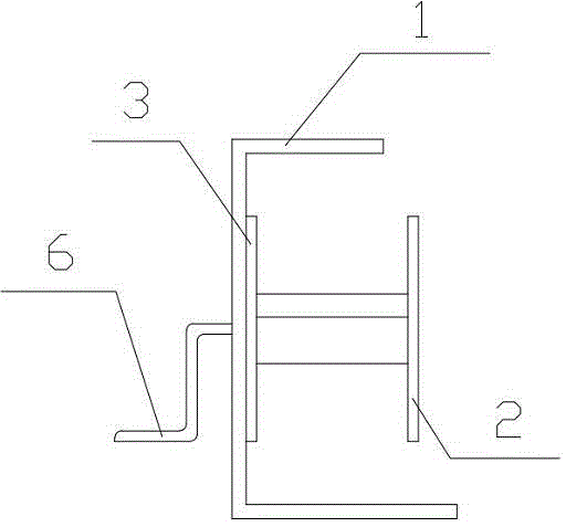
[0021] A pay-off device, comprising a bracket 1 and a runner, the runner is fixed in the middle of the bracket 1; the runner includes a fixed baffle 3, a lead screw 4, a sleeve shaft 5, a telescopic frame, and a movable baffle 2;

[0022] A handle 6 is provided at the outer axis position of the fixed baffle 3, and a lead screw 4 is provided at the inner axis position of the fixed baffle 3, and the handle 6 passes through the fixed baffle 3 and is fixedly connected with one end of the lead screw 4;

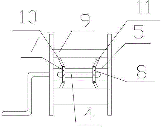
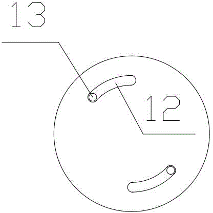
[0023] The sleeve shaft 5 is ring-sleeved on the outside of the lead screw 4, and the sleeve shaft 5 is evenly provided with three longitudinal slotted holes;

[0024] The telescopic frame is made up of the first collar 7, the second collar 8 and three telescopic brackets with the same structure;

[0025] Telescopic bracket is made up of arc plate 9, first support bar 10 and second support bar 11, and arc plate 9 is hinged with first support bar 10, and arc plate 9 is hinged with s...

Embodiment 2

[0033] A pay-off device, comprising a bracket 1 and a runner, the runner is fixed in the middle of the bracket 1; the runner includes a fixed baffle 3, a lead screw 4, a sleeve shaft 5, a telescopic frame, and a movable baffle 2;

[0034] A handle 6 is provided at the outer axis position of the fixed baffle 3, and a lead screw 4 is provided at the inner axis position of the fixed baffle 3, and the handle 6 passes through the fixed baffle 3 and is fixedly connected with one end of the lead screw 4;

[0035] The sleeve shaft 5 is ring-sleeved on the outside of the lead screw 4, and the sleeve shaft 5 is evenly provided with three longitudinal slotted holes;

[0036] The telescopic frame is made up of the first collar 7, the second collar 8 and three telescopic brackets with the same structure;

[0037] Telescopic bracket is made up of arc plate 9, first support bar 10 and second support bar 11, and arc plate 9 is hinged with first support bar 10, and arc plate 9 is hinged with s...

Embodiment 3

[0041] A pay-off device, comprising a bracket 1 and a runner, the runner is fixed in the middle of the bracket 1; the runner includes a fixed baffle 3, a lead screw 4, a sleeve shaft 5, a telescopic frame, and a movable baffle 2;

[0042] A handle 6 is provided at the outer axis position of the fixed baffle 3, and a lead screw 4 is provided at the inner axis position of the fixed baffle 3, and the handle 6 passes through the fixed baffle 3 and is fixedly connected with one end of the lead screw 4;

[0043] The sleeve shaft 5 is ring-sleeved on the outside of the lead screw 4, and the sleeve shaft 5 is evenly provided with three longitudinal slotted holes;

[0044] The telescopic frame is made up of the first collar 7, the second collar 8 and three telescopic brackets with the same structure;

[0045] Telescopic bracket is made up of arc plate 9, first support bar 10 and second support bar 11, and arc plate 9 is hinged with first support bar 10, and arc plate 9 is hinged with s...


PUM


Abstract

The invention discloses a paying-off device which comprises a bracket and a runner, wherein the runner is fixed in the middle of the bracket; the runner comprises a fixed baffle, a lead screw, a sleeve shaft, an expansion bracket and a movable baffle; a handle is arranged at the outside axis of the fixed baffle; the lead screw is arranged at the inside axis of the fixed baffle; the handle penetrates through the fixed baffle and is fixedly connected with one end of the lead screw; the outside of the lead screw is annularly sleeved with a sleeve shaft, and three longitudinal long slotted holes are uniformly formed in the sleeve shaft; the expansion bracket comprises a first lantern ring, a second lantern ring and three expansion supports with the same structure; each expansion support comprises an arc plate, a first supporting rod and a second supporting rod; the lead screw is provided with a first nut and a second nut; the outside of the sleeve shaft is annularly sleeved with the lantern rings; the lantern rings are fixedly connected with the nuts through screws; the screws can slide along the long slotted holes in the sleeve shaft. According to the paying-off device, the structure is simple, the manufacturing cost is low, portability is realized, the diameter of each expansion bracket can be adjusted according to the inner diameter of different wire discs, and the operation is convenient.

Description

technical field [0001] The invention relates to a wire pay-off and belongs to the technical field of electric construction tools. Background technique [0002] In the process of electric power construction or electrical appliance installation, a large number of wires, cables, etc. are usually used, and usually the wires, cables, etc. are packaged in rolls, and the wires need to be released during installation. The traditional unwinding work is that the operator strings up the coiled wires with his hands and then releases them. It often requires two people to cooperate, which is time-consuming and laborious; , Scattered, seriously affecting work efficiency and construction quality. [0003] Common pay-offs on the market have complex structures and single functions, and cannot adjust the diameter of the rotating shaft according to different inner diameters of wire reels. Contents of the invention [0004] The technical problem to be solved by the present invention is to pr...

Claims


Application Information

Patent Timeline
Patent Type & Authority Applications(China)
IPC IPC(8): H02G11/02
Inventor 赵军宪王义常保仓陈东文胡永刚
Owner STATE GRID CORP OF CHINA
Why Eureka
Try Eureka