Charger and construction method thereof

A construction method and charger technology, which is applied in the direction of current collectors, electric vehicles, electrical components, etc., can solve the problems of reduced power utilization of chargers, affecting the quality of AC power supply, and reactive power loss of AC power supply, and achieve low manufacturing costs. The effect of high power utilization rate and wide application range

Inactive Publication Date: 2013-10-02
XIAN GUANCHI ELECTRONICS TECH
View PDF5 Cites 2 Cited by
  • Summary
  • Abstract
  • Description
  • Claims
  • Application Information

AI Technical Summary

Problems solved by technology

[0002] Conventional chargers use transformers, rectifiers, current limiters, batteries and other units to charge the battery with 220V AC. During the charging process, the transformers, current limiters and other units will consume additional power, which will reduce the power utilization of the charger; Conventional chargers use inductive load characteristics and have a low power factor. If the charger is used excessively, it will seriously affect the quality of the AC power supply and cause a large amount of reactive power loss. When the conventional charger is used in an exposed environment, The battery casing, all components, connecting wires and other metal parts may be charged, and it is very unsafe to use

Method used


Image

  • Charger and construction method thereof
  • Charger and construction method thereof
  • Charger and construction method thereof

Examples


Embodiment 1

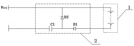
[0020] Embodiment 1: see figure 1 , the charger constructed by the above method includes a charging unit 2 that connects the battery 1 to a power supply, the power supply is a 220V, 50Hz single-phase AC power supply, including live wires and neutral wires, and the charging unit 2 includes a high-voltage capacitor C1, a first rectifier Diode D1 and the second rectifying diode D2, one end of the high-voltage capacitor C1 is connected to the live wire, the other end is connected to the negative pole of the first rectifying diode D1, the positive pole of D1 is connected to the negative pole of the battery 1, the positive pole of the battery is connected to the neutral line, and the negative pole of the second rectifying diode D2 is connected to The neutral line, the anode of D2 is connected to the connection point of the high voltage capacitor C1 and the first rectifier diode D1.

Embodiment 2

[0021] Example 2: see figure 2 , the power live wire and the zero line are provided with a linkage switch and a discharge resistor R1. The linkage switch is a double-pole single-throw switch or any form of contact switch, which can be a commercial switch or self-made by a metal sheet. The present invention uses a double Single-pole single-throw switch; when the battery door is opened, the switch is turned off, and the charger is physically isolated from the AC grid; when the battery door is closed, the switch is closed and charging starts; a discharge resistor is connected in parallel to the AC power supply or the high-voltage capacitor C1, and the resistance value Greater than 510 kΩ.

[0022] A linkage switching switch and a discharge resistor R1 are set on the live wire and the zero line of the power supply. The linkage switching switch is a double-pole single-throw switch or any form of contact switch, which can be a commodity switch or made by a metal sheet. The present ...

Embodiment 3

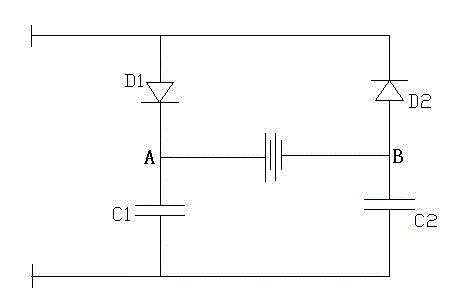
[0028] Embodiment 3: see image 3 A charger with another circuit structure constructed by the above method includes a charging unit 2 connected to a battery 1 and an AC power supply, the AC power supply includes live wires and neutral wires, and the live wires and neutral wires are respectively connected in series with the first A rectifier diode D1, a high-voltage capacitor C1, a second rectifier diode D2, and a high-voltage capacitor C2, and a battery 1 is connected in series between the first rectifier diode D1 and the second rectifier diode D2.

[0029] Application of Embodiment 1: philishave 46 rechargeable electric shaver produced by philips company, the original charging part circuit is removed, and the high-voltage capacitor C1, the first rectifier diode D1 and the second rectifier diode D2 are figure 1 The circuit is connected to form a charging unit, and all the charging units are placed in an insulating shell, and then the charging unit is connected to the battery. ...


PUM


Abstract

The invention relates to a charger and a construction method thereof. The conventional charger employs inductive load characteristics, and is lower in power factor; if the charger is used excessively, the quality of an alternating current power supply can be influenced seriously; reactive loss of the alternating current power supply is caused greatly; and a battery case, all components, connecting wires and other metal parts are electrified possibly when the charger is used in an exposed environment, so that the use is very unsafe. According to the construction method of the charger, a battery is charged when a capacitor is charged in an alternating current circuit. The charger can reduce the reactive loss of the power supply and manufacturing cost, saves electric energy, and can be used safely in any environment.

Description

technical field [0001] The invention relates to a charger and a construction method thereof. Background technique [0002] Conventional chargers use transformers, rectifiers, current limiters, batteries and other units to charge the battery with 220V AC. During the charging process, the transformers, current limiters and other units will consume extra power, which will reduce the power utilization of the charger; Conventional chargers use inductive load characteristics and have a low power factor. If the charger is used excessively, it will seriously affect the quality of the AC power supply and cause a large amount of reactive power loss. When the conventional charger is used in an exposed environment, The battery casing, all components, connecting wires, and other metal parts may be charged and are unsafe to use. Contents of the invention [0003] The technical problem to be solved by the present invention is to provide a charger and its construction method that can sav...

Claims


Application Information

Patent Timeline
Patent Type & Authority Applications(China)
IPC IPC(8): H02J7/00
Inventor 周克鸣武永斌
Owner XIAN GUANCHI ELECTRONICS TECH
Why Eureka
Try Eureka