
A control method for a high voltage ratio bidirectional DC converter

A bidirectional DC conversion and control method technology, applied in the direction of converting DC power input to DC power output, adjusting electrical variables, and controlling/regulating systems, etc., can solve the problem of deteriorating electromagnetic compatibility performance of converters, large current stress of switching tubes, and switching Improve the electromagnetic compatibility performance, reduce the current stress, and reduce the voltage peak

Inactive Publication Date: 2015-10-28
NANJING UNIV OF AERONAUTICS & ASTRONAUTICS
View PDF3 Cites 0 Cited by
  • Summary
  • Abstract
  • Description
  • Claims
  • Application Information

AI Technical Summary

Problems solved by technology

[0003] In recent years, the voltage transformation ratio of the isolated bidirectional DC converter proposed by scholars is VL / VH = D / N. In the case of a large difference in the power supply voltage levels at both ends, the voltage transformation ratio of the converter can only be increased by increasing the transformer turn ratio. Ratio, but the increase of the transformer turns ratio increases the leakage inductance, and the resonance between the leakage inductance and the junction capacitance of the switch tube causes a voltage spike, which not only increases the voltage stress of the switch tube, but also deteriorates the electromagnetic compatibility performance of the converter
In addition, most of the existing bidirectional DC converters have two bridge arms. In high-power applications, the switching tubes are subjected to large current stress, making it difficult to select the switching tubes.

Method used


Image

  • A control method for a high voltage ratio bidirectional DC converter
  • A control method for a high voltage ratio bidirectional DC converter
  • A control method for a high voltage ratio bidirectional DC converter

Examples


Embodiment Construction

[0014] The present invention will be described in further detail below in conjunction with the accompanying drawings and specific embodiments.

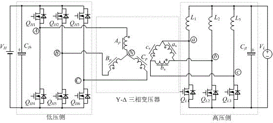
[0015] figure 1 It is the circuit principle diagram of the high voltage ratio bidirectional DC converter of the present invention, C fh is the high-voltage side filter capacitor, C fl is the low-voltage side filter capacitor, Q H1 , Q H2 , Q H3 , Q H4 , Q H5 , Q H6 , Q L1 , Q L2 and Q L3 for the switch tube, L 1 , L 2 and L 3As a filter inductor, the Y-shaped winding of the Y-Δ three-phase transformer is composed of A p phase winding, B p phase winding and C p Composed of phase windings, the Δ winding of the Y-Δ three-phase transformer is composed of a s phase winding, b s phase winding and c s Composed of phase windings, the input source of the high voltage side is the DC bus V H , the low-voltage side input source is the battery V L . filter capacitor C fh In parallel with the DC bus, the...


PUM


Abstract

The invention discloses a high-voltage transmission ratio bidirectional DC converter and a control method thereof. The high-voltage transmission ratio bidirectional DC converter mainly comprises a high-voltage side three-phase full-bridge consisting of six switch tubes, a Y-delta shaped three-phase transformer and a low-voltage side three-phase bridge arm consisting of three filtering inductors and three switch tubes. The invention also provides a control method of the high-voltage transmission ratio bidirectional DC converter. The internal characteristics and the control mode of the Y-delta shaped three-phase transformer are utilized to improve the voltage transformation ratio by one time in comparison with a traditional bidirectional DC converter, so that the turn ratio of the transformer is reduced by one time, and the leakage inductance is greatly reduced, the electromagnetism compatibility of the transformer is improved. The low-voltage side three-phase inductors are parallelly connected in a staggered manner, and the output current ripple is greatly reduced after the three-phase current ripples are stacked, so that the service life of a storage battery can be favorably prolonged, and the size of a filter is favorably reduced. The high voltage side and the low voltage side both adopt the three-phase staggered shunt-wound structure, so that the current stress of the switch tubes is reduced and suitable switch tubes can be conveniently selected for high-power application occasions.

Description

technical field [0001] The invention relates to a control method of a high voltage ratio bidirectional DC converter, in particular to a control method of a high voltage ratio bidirectional DC converter using a three-phase transformer, and belongs to the fields of new energy generation and power electronic conversion. Background technique [0002] With the increasingly serious energy crisis and environmental pollution, the development and utilization of new energy sources such as solar energy, wind energy, and hydrogen energy have attracted more and more attention. Due to the limitation of weather and climate conditions, new energy has the disadvantages of unstable and discontinuous power supply. In order to make up for the uncertainty of new energy sources such as solar energy, batteries are introduced into the new energy combined power supply system as a backup energy source. When the electric energy generated by new energy sources is not enough to provide the energy requir...

Claims


Application Information

Patent Timeline
Patent Type & Authority Patents(China)
IPC IPC(8): H02M3/335H02M1/14
Inventor 金科刘畅
Owner NANJING UNIV OF AERONAUTICS & ASTRONAUTICS
Learn More