Punching machine

A punching machine and punch technology, applied in the field of punching machines, can solve the problems of inability to integrate equipment, high input cost, large cost expenditure, etc., and achieve the effect of reducing labor intensity, ingenious design structure, and reducing production cost.

Active Publication Date: 2013-10-09
舟山神鹰滤清器制造有限公司
View PDF14 Cites 25 Cited by
  • Summary
  • Abstract
  • Description
  • Claims
  • Application Information

AI Technical Summary

Problems solved by technology

However, compared with the stamping machine tools currently owned and widely used by production enterprises, the above-mentioned devices cannot integrate the original equipment, but need to be repurchased, resulting in greater cost expenditure
[0004] The existing technology cannot coordinate the relationship between the safety, efficiency and cost of the stamping machine well. There are problems of low efficiency and high risk factor, or high efficiency and safety but the need to purchase new equipment leads to high investment costs.

Method used


Image

  • Punching machine
  • Punching machine
  • Punching machine

Examples


Embodiment Construction

[0018] The present invention will be further described in detail below with reference to the embodiments of the accompanying drawings.

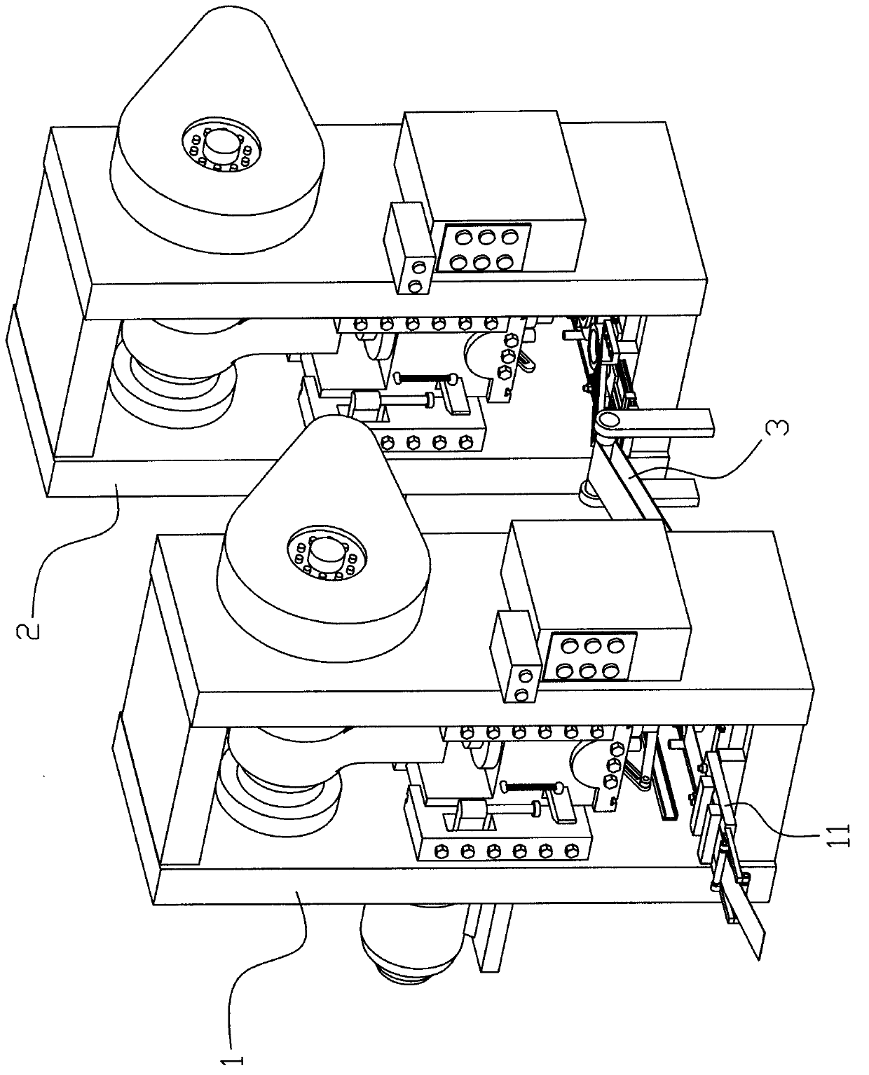
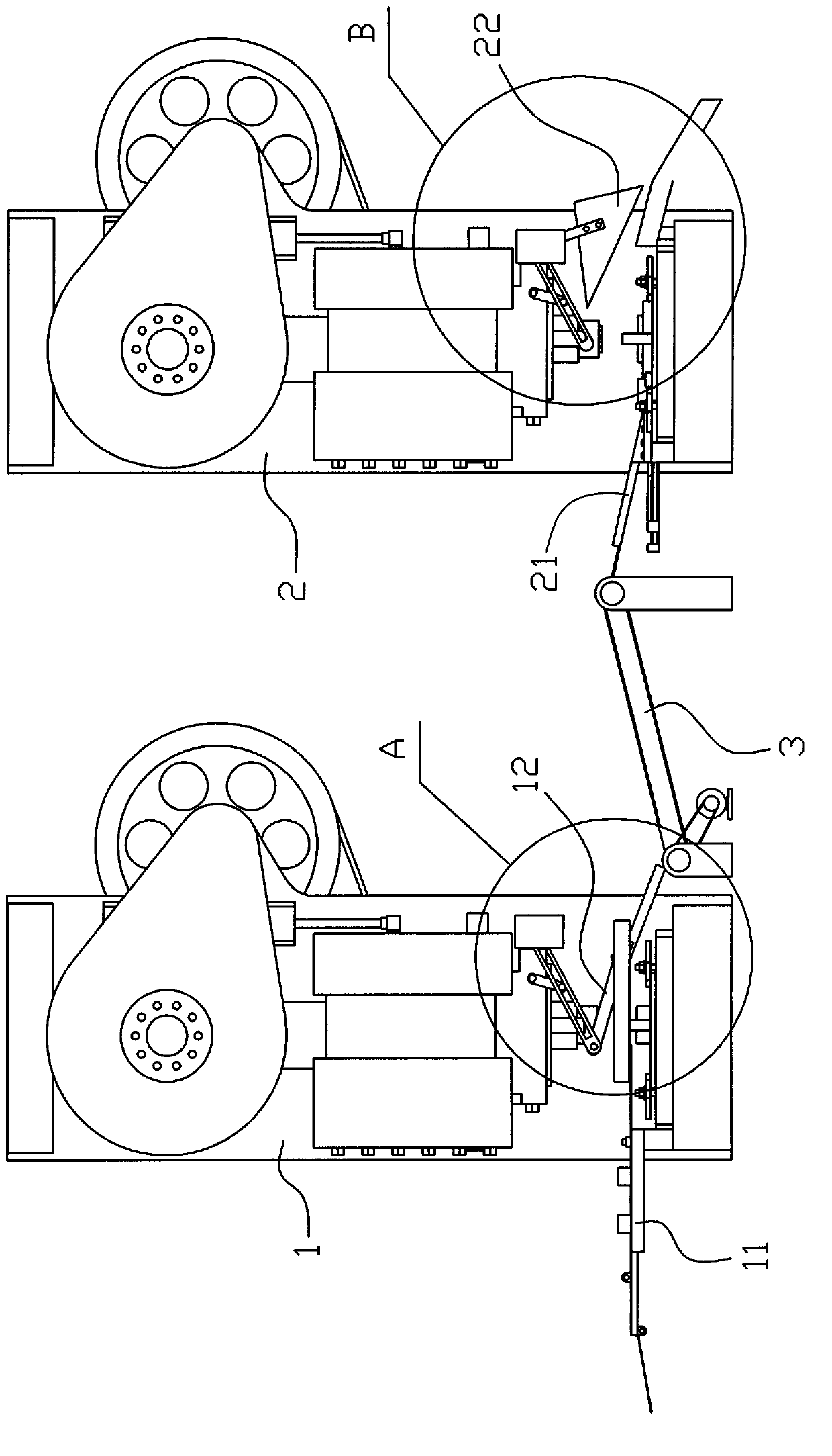
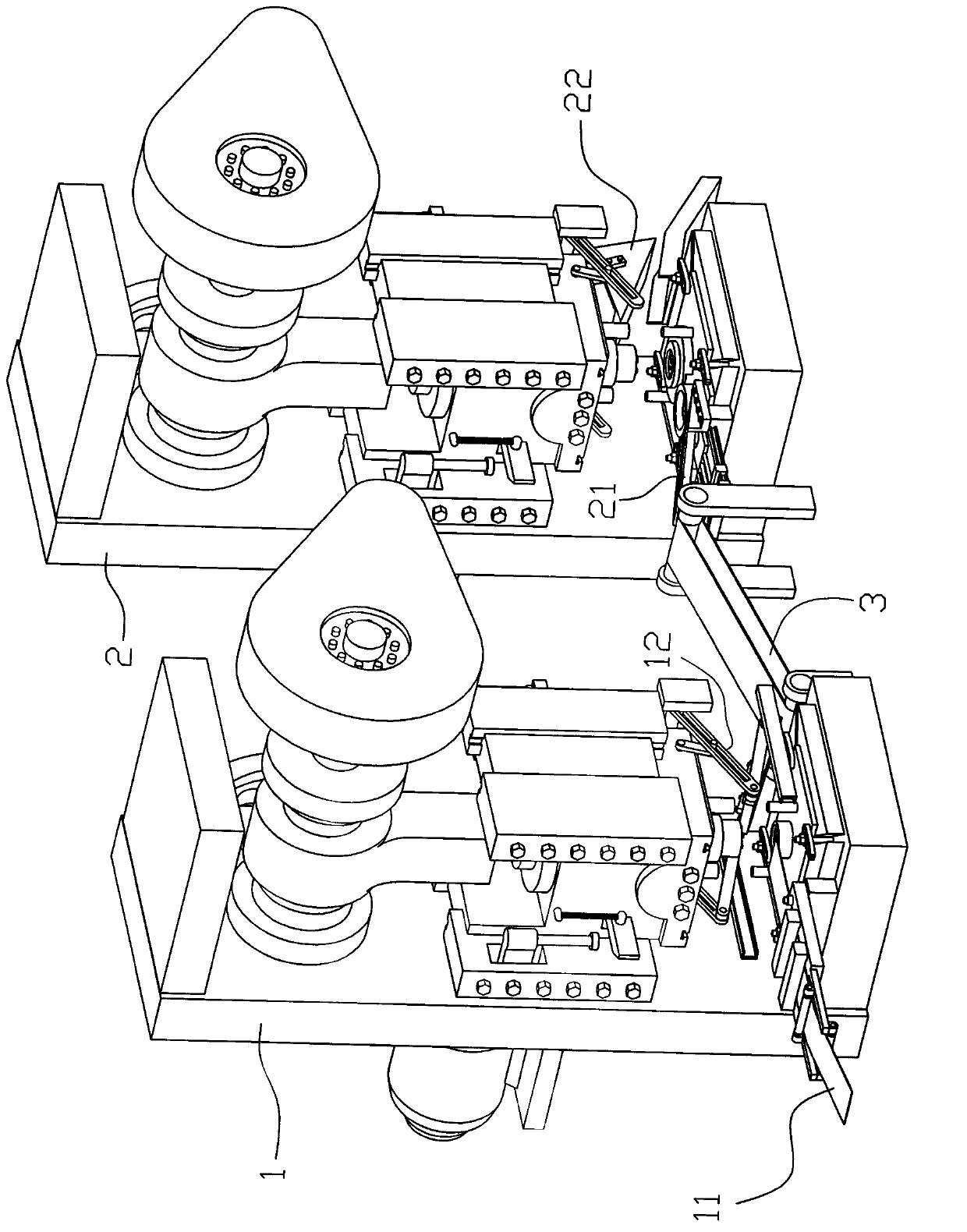
[0019] like Figure 1 to Figure 6 As shown, the punching machine of this embodiment includes a first punching machine 1, a second punching machine 2, and also includes a steel strip feeding device 11, a first discharging device 12, a workpiece feeding device 21, and a second discharging device. 22 and the conveying device 3; the steel strip feeding device 11 and the first discharging device 12 are horizontally installed on the first punch 1; the workpiece feeding device 21 and the second discharging device 22 are horizontally installed on the On the second punching machine 2; the conveying device 3 is arranged between the first discharging device 12 on the first punching machine and the workpiece feeding device 21 on the second punching machine, and the workpieces from the first discharging device 12 are sent to On the conveying device 3, th...


PUM


Abstract

Disclosed is a punching machine. The punching machine comprises a first punching machine (1) and a second punching machine (2), and further comprises a steel strip feeding device (11), a first discharging device (12), a workpiece feeding device (21), a second discharging device (22) and a conveying device (3). The steel strip feeding device and the first discharging device are horizontally installed on the first punching machine and synchronously work with the first punching machine in a coordinated mode; the workpiece feeding device (21) and the second discharging device (22) are horizontally installed on the second punching machine (2) and synchronously work with the second punching machine (2) in a coordinated mode; the conveying device (3) is arranged between the steel strip feeding device (11) arranged on the first punching machine (1) and the workpiece feeding device (21) arranged on the second punching machine (2). The punching machine has the advantages of being ingenious in structural design because two punching machines are integrated through an automatic conveying device, and therefore the purpose of continuously machining workpieces is achieved, reducing labor intensity, substantially improving production efficiency of product machining, and effectively reducing production cost of labor force.

Description

technical field [0001] The invention relates to a punching machine, in particular to a two-in-one punching machine. Background technique [0002] In the process of processing some equipment parts, it may be necessary to go through multiple stamping processes. To complete each stamping process, an independent stamping machine is generally required, so that the workpiece must be transferred from one stamping machine to another during processing. The machine requires a lot of manual operations, which affects the production efficiency, and the manual operation is more dangerous. At present, during the stamping process, safety accidents such as broken fingers still occur from time to time. [0003] The authorization announcement number is CN202219284U, and the patent named a multi-station continuous punching machine discloses a technical solution. The punching device can punch those punching parts that require multiple punching processes to finally complete the punching, and has ...

Claims


Application Information

Patent Timeline
Patent Type & Authority Applications(China)
IPC IPC(8): B21D22/02B21D43/02B21D45/00
Inventor 任贤安任宏斌
Owner 舟山神鹰滤清器制造有限公司
Why Eureka
Try Eureka