Battery shell automatic notching die

A technology of battery casing and slit die, applied in metal processing equipment, forming tools, manufacturing tools, etc., can solve the problems of poor production efficiency, low production efficiency, large product burrs, etc., so as to reduce production costs and improve work production efficiency. Effect

Inactive Publication Date: 2013-10-09
倪志华
View PDF5 Cites 4 Cited by
  • Summary
  • Abstract
  • Description
  • Claims
  • Application Information

AI Technical Summary

Problems solved by technology

[0004] The mouth of this four-knife incision shell is divided into four cuts, and the work efficiency is slow. During the incision process, the shell is repeatedly positioned, and the dimensional accuracy after the mouth incision has a certain deviation
[0005] 2. Rotary cutting method. Before the shell is cut, the positioning block should be placed in the inner cavity of the shell. After the cutting is completed, the positioning block will be taken out. These two actions must be repeated for each cutting work. The accuracy of the shell mouth is guaranteed, but Poor production efficiency, manual operation is required, and automatic production cannot be completed
[0006] The above incision method has slow production speed, low production efficiency and high risk
The inner guide rail of the lower mold is prone to inclination, and the products produced have large burrs, high scrap rate, high cost, and cannot enter the multi-station automatic production line

Method used


Image

  • Battery shell automatic notching die
  • Battery shell automatic notching die
  • Battery shell automatic notching die

Examples


Embodiment Construction

[0026] The present invention will be further described below in conjunction with accompanying drawing and specific embodiment:

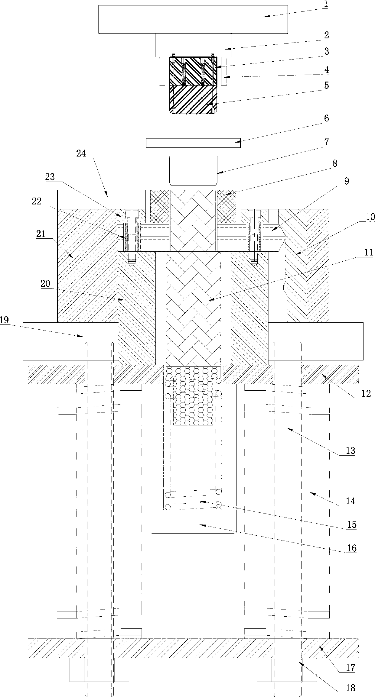
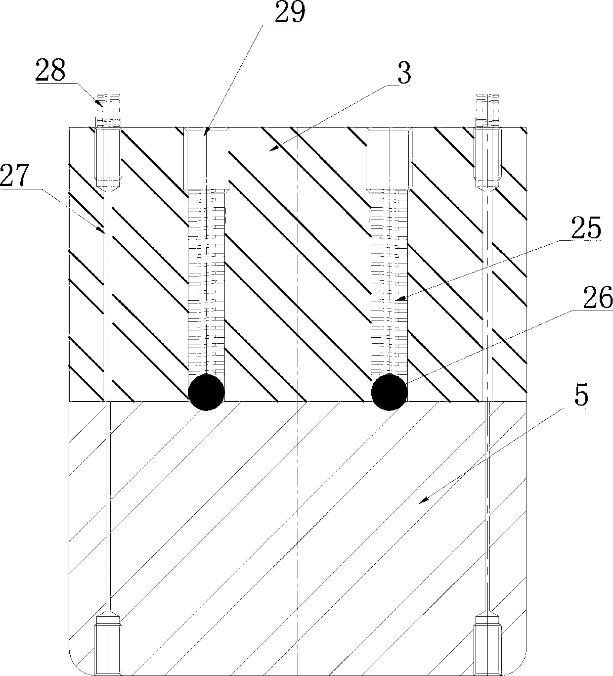
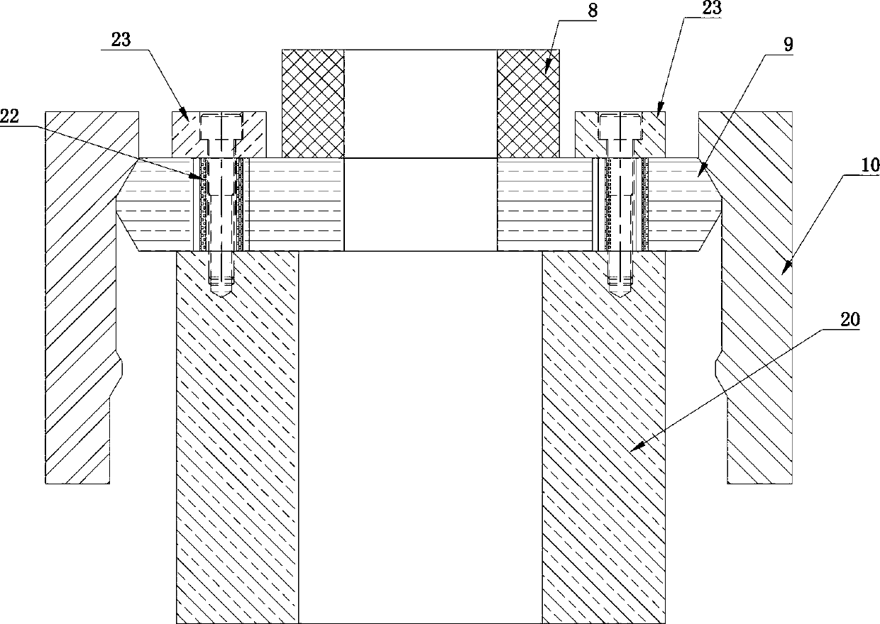
[0027] A kind of battery casing automatic cutting die, such as Figure 1 to Figure 7 As shown, it includes an upper mold and a lower mold. The upper mold includes an upper template 1, and the upper template 1 is fixedly connected with a slit punch fixing plate 2, and the slit punch fixing plate 2 is fixedly connected with a slit punch 3 and a positioning rod 4. The positioning rod 4 is located around the notch punch 3, and the front, rear, left, and right sides of the notch punch 3 are movably connected with a positioning core 5; There is a die cover plate 24, and a perforation is arranged in the middle of the die cover plate 24; a lower positioning seat 20 is movable up and down in the middle of the lower mold base 21 and the lower template 19, and a guide slider 9 is arranged on the lower positioning seat 20, and the guiding slider 9 is arranged on...


PUM


Abstract

A battery shell automatic notching die comprises an upper die and a lower die. The upper die comprises an upper die plate, a notching male die fixing plate is fixedly connected with the lower face of the upper die plate, the lower face of the notching female die fixing plate is fixedly connected with a notching male die and locating rods, the locating rods are located around the notching male die, and locating cores are movably connected with the lower face of the notching male die in a front-and-back and left-and-right mode. The lower die comprises a lower die plate, a lower die seat is fixedly connected with the upper face of the lower die plate, female die cover plates are fixedly connected with the upper face of the lower die seat, and penetrating holes are formed in the middle of the female die cover plates. The middle part of the lower die seat and the middle part of the lower die plate are movably connected with a lower locating seat together in an up-and-down mode, guiding sliding blocks are arranged on the upper face of the lower locating seat, upper locating rings are arranged on the upper faces of the guiding sliding blocks, the upper locating rings, the guiding sliding blocks and the lower locating seat are fixedly connected through equal-altitude sleeves, guiding sliding rails are arranged between the lower die seat and the lower locating seat, the guiding sliding rails are fixedly installed inside the lower die seat and the upper face of the lower die plate, the guiding sliding blocks correspond to the guiding sliding rails, and the guiding sliding blocks are connected with the guiding sliding rails in an up-and-down sliding mode.

Description

technical field [0001] The invention relates to a battery case notch die, in particular to an automatic battery case notch die. Background technique [0002] At present, the incision mold used to produce the battery casing is a separate incision mold. After the casing is stretched, it must be transferred to the incision production line. There are two main incision methods for traditional casing products with high mouth size requirements: [0003] 1. In the traditional four-knife incision method, the remaining material at the mouth of the shell is first cut off the two opposite sides, and then the remaining two opposite sides are cut off. [0004] The mouth of this four-knife incision shell is cut off four times, and the work efficiency is slow. During the incision process, the shell is repeatedly positioned, and the dimensional accuracy after the mouth incision has a certain deviation. [0005] 2. Rotary cutting method. Before the shell is cut, the positioning block should ...

Claims


Application Information

Patent Timeline
Patent Type & Authority Applications(China)
IPC IPC(8): B21D28/14B21D37/12
Inventor 倪志华
Owner 倪志华
Why Eureka
Try Eureka