Fixture for machining outer circle of commutator
A commutator and fixture technology, applied in the direction of manufacturing tools, metal processing equipment, metal processing machinery parts, etc., can solve the problems of increased positioning error, inner hole capping, and low product processing efficiency, so as to reduce the number of repeated positioning , Reduce processing errors, reduce the effect of bad probability
- Summary
- Abstract
- Description
- Claims
- Application Information
AI Technical Summary
Problems solved by technology
Method used
Image

Examples
Embodiment Construction
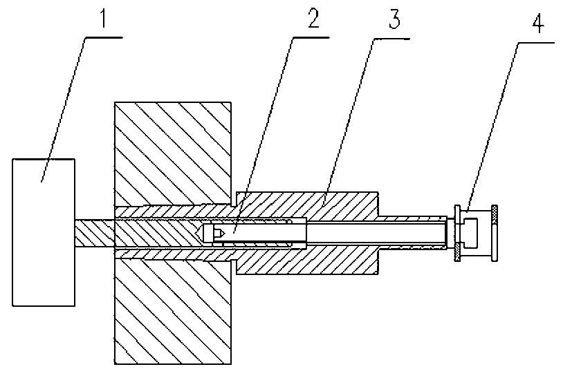
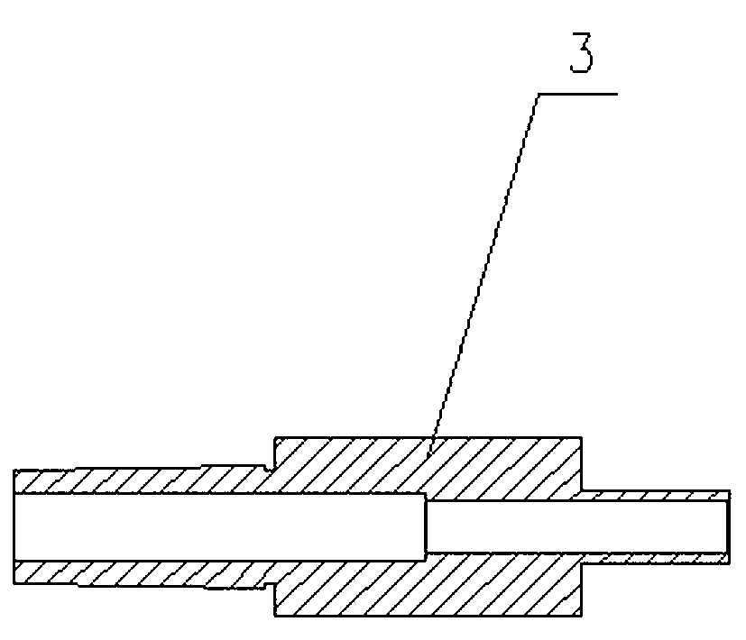
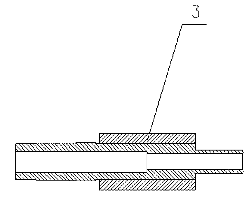
[0013] Such as figure 1 As shown, this kind of jig for processing the outer circle of the commutator includes a cylinder 1, a pull rod 2, a positioning mandrel 3 and a positioning block 4. The pull rod 2 is connected to the cylinder 1 through threads, and the pull rod 2 is located at In the positioning mandrel 3 , the tail of the pull rod 2 is configured as an I-shaped groove 5 structure, and the positioning block 4 is placed in the groove 5 . When processing the commutator, put the inner hole of the commutator on the head of the positioning mandrel 3, and then place the positioning block 4 into the I-shaped groove 5 of the pull rod 2 in the correct way, and the pull rod 2 The positioning block 4 is tightened under the pulling force of the cylinder 1, thereby positioning the commutator. The positioning mandrel 3 in this embodiment is composed of a shaft sleeve 6 and a core rod 7, and the shaft sleeve 6 and the core rod 7 are connected in a threaded manner. With this structur...
PUM
 Abstract
Description
Claims
Application Information
 - R&D
- Intellectual Property
- Life Sciences
- Materials
- Tech Scout
- Unparalleled Data Quality
- Higher Quality Content
- 60% Fewer Hallucinations
Browse by: Latest US Patents, China's latest patents, Technical Efficacy Thesaurus, Application Domain, Technology Topic, Popular Technical Reports.
© 2025 PatSnap. All rights reserved.Legal|Privacy policy|Modern Slavery Act Transparency Statement|Sitemap|About US| Contact US: help@patsnap.com