This helps you quickly interpret patents by identifying the three key elements:
Problems solved by technology
Method used
Benefits of technology
Problems solved by technology
[0003] The purpose of the present invention is to solve the problem that the existing inoculation loop and applicator need to be held in the hand after being sterilized by alcohol lamp flame dry heat during experimental operation, and the culture medium after it is cooled and steam sterilized can only be judged by experience. The problem that its temperature affects the accuracy of the test results provides a sterilizable assembly bracket for aseptic manipulation experiments
Method used
Image
Click on the blue label to locate the original text in one second.
Reading with bidirectional positioning of images and text.
Examples
specific Embodiment approach 1
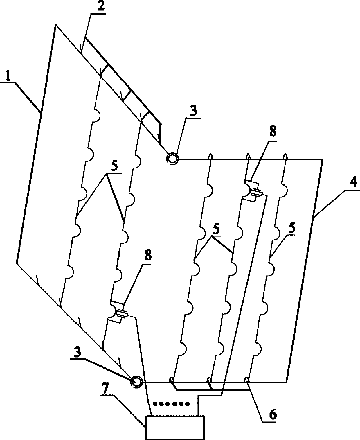
[0007] Specific implementation mode one: combine figure 1 Describe this embodiment, the sterilizable assembly bracket for the aseptic operation experiment described in this embodiment, which includes a frame 1, a retaining wire 2, a connector 3, a bottom frame 4, and a heat-resistant rod with a plurality of semicircular positioning rings 5. Connecting ring 6, temperature display control unit 7 and N temperature sensors 8, N is an integer greater than or equal to 1, frame 1 and bottom frame 4 are U-shaped frames with the same size, and frame 1 and bottom frame 4 pass through connectors 3 connections, frame 1 U-shaped arms are symmetrically provided with multiple retaining wires 2, heat-resistant rods 5 are placed horizontally on the retaining wires 2, bottom frame 4 U-shaped arms are symmetrically provided with multiple connecting rings 6, and heat-resistant rods 5 are fixed on The connection ring 6 is parallel to the heat-resistant rod 5 on the frame 1, and N temperature senso...
specific Embodiment approach 2
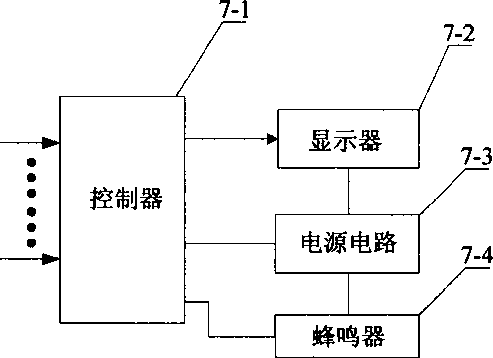
[0009] Specific implementation mode two: combination figure 2 Describe this embodiment. This embodiment is a further limitation of the aseptic operation experiment sterilizable assembly bracket described in Embodiment 1. The temperature display control unit 7 includes a controller 7-1, a display 7-2, and a power circuit 7- 3 and buzzer 7-4, the power output end of power supply circuit 7-3 corresponds to the power input end of controller 7-1, the power input end of display 7-2 and the power input end of buzzer 7-4 respectively Connected, the input ends of the N temperature sensing signals of the controller 7-1 are correspondingly connected with the output ends of the sensing signals of the N temperature sensors 8, and the output ends of the display signals of the controller 7-1 are connected with the output ends of the display 7-2. The input end of the display signal is connected, and the output end of the buzzer start control signal of the controller 7-1 is connected with the...
specific Embodiment approach 3
[0010] Specific implementation mode three: combination figure 2 This embodiment is described. This embodiment is a further limitation of the aseptic operation experiment sterilizable assembly bracket described in Embodiment 2, and the controller 7-1 adopts a single-chip microcomputer.
[0011] Specific implementation mode four: combination figure 1 This embodiment is described. This embodiment is a further limitation of the aseptic operation experiment sterilizable assembly bracket described in Embodiment 1. The positioning rings on the heat-resistant rod 5 are evenly distributed.
[0012] Specific implementation mode five: combination figure 1 This embodiment is described. This embodiment is a further limitation of the aseptic operation experiment sterilizable assembly bracket described in Embodiment 1. Both the frame 1 and the bottom frame 4 are heat-resistant frames.
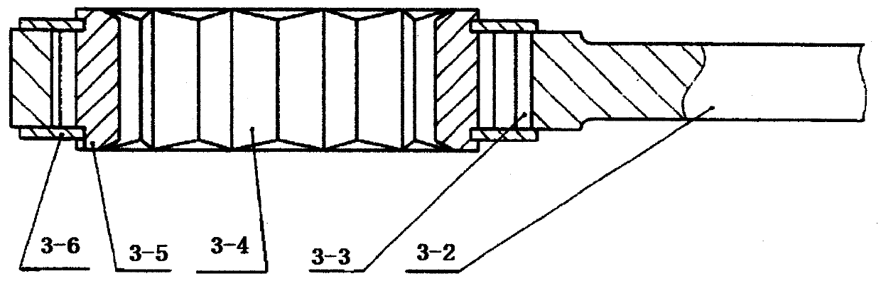
[0013] Specific implementation mode six: combination image 3 , Figure 4 This embodiment is describe...
PUM
Abstract
The invention discloses a sterilizable assembly bracket for a sterile operation experiment, and relates to a supporting device in microorganism and cell culture experiments, aiming at solving the problem that the accuracy of a test result is affected since the conventional inoculation ring and coater are required to be held in hand to cool after being subjected to dry heat sterilization by using an alcohol lamp and the temperature of an evaporated and sterilized culture medium can only be judged empirically. The sterilizable assembly bracket comprises a border, stop wires, connecting pieces, a bottom frame, heat-resistant rods, connecting rings, a temperature display control unit and N temperature sensors, wherein the border is connected with the bottom frame through the connecting pieces; the opposite surfaces of the border and the bottom frame are provided with a plurality of stop wires; the two ends of each heat-resistant rod are correspondingly arranged on the symmetric strop wires respectively; the upper surface of the bottom frame is provided with a plurality of connecting rings; the two ends of the heat-resistant rods are correspondingly arranged in the symmetric connecting rings respectively; the N temperature sensors are communicated with the temperature display control unit. The sterilizable assembly bracket is applicable to the supporting device for vertical cell culture of a square culture vessel in the cell culture experiment.
Description
technical field [0001] The present invention relates to support devices in microbiological and cell culture experiments. Background technique [0002] At present, the inoculation ring and applicator in the ultra-clean workbench are placed flat on the table. During the experimental operation, after dry heat sterilization with an alcohol lamp flame, it needs to be held in the hand until it cools down, which is inconvenient to use; especially When inoculating multiple bacteria or coating different plates, it is necessary to perform flame dry heat sterilization one after another, which is very time-consuming. The temperature of the burnt inoculation loop, applicator, and steam-sterilized medium can only be judged by experience, and sometimes inaccurate judgments affect the test results, which seriously affects the test efficiency. In addition, there is no effective support for the vertical cultivation of the square culture dish in the incubator. Contents of the invention [...
Claims
Application Information
Patent Timeline
Application Date:The date an application was filed.
Publication Date:The date a patent or application was officially published.
First Publication Date:The earliest publication date of a patent with the same application number.
Issue Date:Publication date of the patent grant document.
PCT Entry Date:The Entry date of PCT National Phase.
Estimated Expiry Date:The statutory expiry date of a patent right according to the Patent Law, and it is the longest term of protection that the patent right can achieve without the termination of the patent right due to other reasons(Term extension factor has been taken into account ).
Invalid Date:Actual expiry date is based on effective date or publication date of legal transaction data of invalid patent.

