Heat-pump water heater and defrosting control method

A heat pump water heater and control device technology, applied to fluid heaters, refrigerators, refrigeration components, etc., can solve the problems of blocked air flow, long defrosting time, incomplete defrosting, etc., achieve complete defrosting, and speed up defrosting. time, the effect of improving defrosting efficiency

Inactive Publication Date: 2013-10-09
GD MIDEA HEATING & VENTILATING EQUIP CO LTD +1
View PDF3 Cites 8 Cited by
  • Summary
  • Abstract
  • Description
  • Claims
  • Application Information

AI Technical Summary

Problems solved by technology

However, when the heat pump water heater operates in winter when the outdoor temperature is low, the surface temperature of the outdoor finned evaporator will reach below zero, and frost may form on the surface of the evaporator. The thick frost layer will block the air flow and affect the heat pump water heater. The hot water heating capacity; long-term operation may lead to a protective shutdown of the system, thus affecting the life of the machine
[0003] At present, heat pump water heaters mainly adopt two ways to defrost: one is to stop the defrost and let the frost melt by itself. The compressor system of the water heater provides hot water
The other is to change the flow direction of the working fluid through the reversing valve to perform reverse cycle defrosting, and melt the frost through the heat consumed by the compressor. This method cannot provide hot water through the compressor system of the heat pump water heater, and even needs to absorb heat from water or Defrost can only be defrosted by auxiliary electric heating, and defrosting may not be complete

Method used


Image

  • Heat-pump water heater and defrosting control method
  • Heat-pump water heater and defrosting control method
  • Heat-pump water heater and defrosting control method

Examples


Embodiment Construction

[0038] The technical solutions of the present invention will be further described below in conjunction with the accompanying drawings and specific embodiments. It should be understood that the specific embodiments described here are only used to explain the present invention, not to limit the present invention.

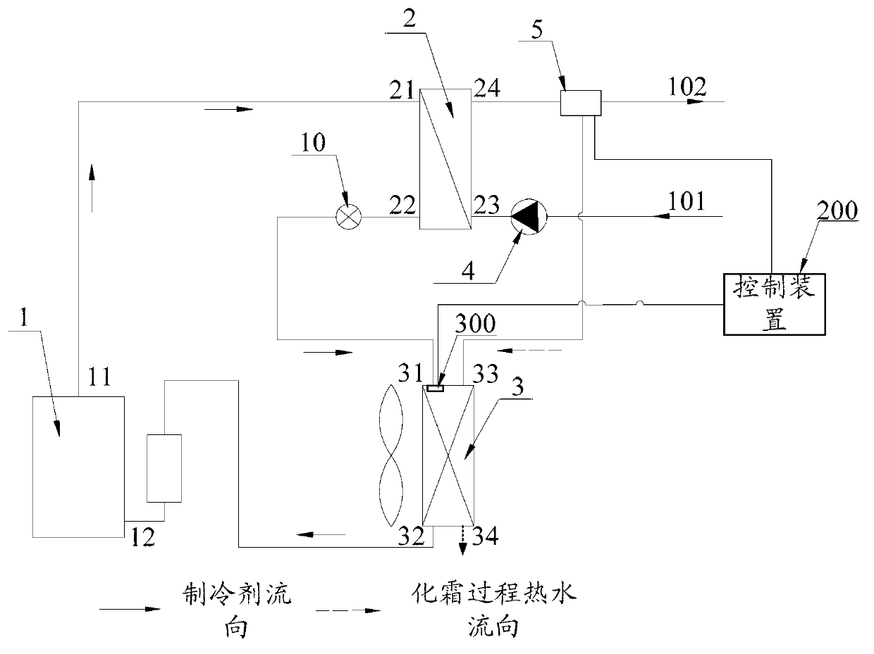
[0039] refer to figure 1 , presents a schematic structural view of the first embodiment of the heat pump water heater of the present invention. The heat pump water heater in this embodiment includes a compressor 1 , a condenser 2 , a throttling component 10 , an evaporator 3 , a water extraction device 4 , and a flow distribution device 5 . Wherein, the compressor 1 has an air outlet 11 and an air inlet 12 . The condenser 2 has a working fluid inlet 21 , a working fluid outlet 22 , a water inlet 23 and a water outlet 24 . The evaporator 3 has a working fluid inlet 31 , a working fluid outlet 32 ​​, a water inlet 33 and a water outlet 34 . The gas outlet 11 of the ...


PUM


Abstract

The invention discloses a heat-pump water heater. The heat-pump water heater comprises a compressor, a condenser, a throttling assembly, an evaporator, a water pumping device, a shunting device, a temperature detection device and a control device. One end of the water pumping device is connected with a water inlet pipe, the other end of the water pumping device is connected with a water inlet of the condenser, and the water pumping device is used for pumping water into the condenser. The inlet end of the shunting device is connected with a water outlet of the condenser, one outlet end of the shunting device is connected with a water outlet pipe, the other outlet end of the shunting device is correspondingly connected with a water inlet of the evaporator, and the shunting device is used for shunting water flowing out of the condenser. The temperature detection device is arranged in the position of an evaporator working medium inlet and used for detecting the temperature T of the position of the evaporator working medium inlet. The control device is connected with the temperature detection device and the shunting device and used for controlling shunting of the shunting device according to the temperature T, and therefore defrosting can be conducted. The invention further discloses a defrosting control method of the heat-pump water heater. The defrosting control method achieves the purpose of defrosting and will not hinder water heating of the heat-pump water heater.

Description

technical field [0001] The invention relates to the field of water heaters, in particular to a heat pump water heater and a defrosting control method thereof. Background technique [0002] The heat pump water heater is a device that uses the reverse Carnot principle to transfer the heat in the air to the water through the working medium to produce hot water. When the heat pump water heater is working, it only consumes a part of energy, that is, the work consumed by the entire heat pump water heater is only a small part of the output work, so the heat pump water heater can save a lot of electricity. However, when the heat pump water heater operates in winter when the outdoor temperature is low, the surface temperature of the outdoor finned evaporator will reach below zero, and frost may form on the surface of the evaporator. The thick frost layer will block the air flow and affect the heat pump water heater. The hot water heating capacity; long-term operation may cause a pro...

Claims


Application Information

Patent Timeline
Patent Type & Authority Applications(China)
IPC IPC(8): F24H4/02F25B47/02
Inventor 曾光明
Owner GD MIDEA HEATING & VENTILATING EQUIP CO LTD
Why Eureka
Try Eureka