Optical fiber connection state detecting method and optical fiber connection state detecting device

A connection detection and optical fiber connection technology, applied in the field of communication, can solve the problems of reducing network element online efficiency, network commissioning efficiency, failure to detect correct network element fiber connection, failure to send detection messages and test messages, etc.

Active Publication Date: 2013-10-09
HUAWEI TECH CO LTD
View PDF7 Cites 1 Cited by
  • Summary
  • Abstract
  • Description
  • Claims
  • Application Information

AI Technical Summary

Problems solved by technology

[0005] However, for the above detection process, when the working modes of the optical fiber interfaces connecting the two network elements do not match, if the optical fiber interface is wrongly inserted, it may cause the optical fiber interface of the network element to be unable to open, so that the corresponding information cannot be sent and received. detection packets and test messages; when the optical fiber ne

Method used


Image

  • Optical fiber connection state detecting method and optical fiber connection state detecting device
  • Optical fiber connection state detecting method and optical fiber connection state detecting device
  • Optical fiber connection state detecting method and optical fiber connection state detecting device

Examples


Embodiment 1

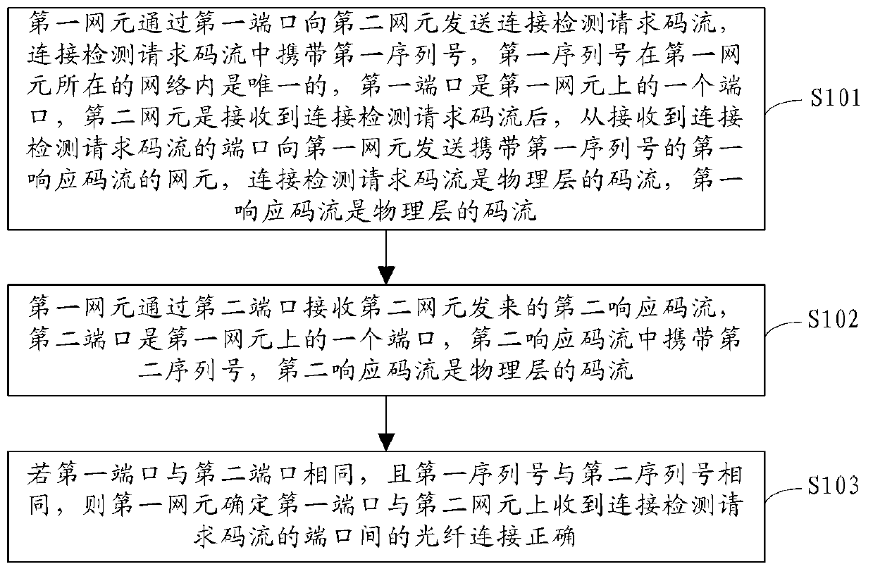
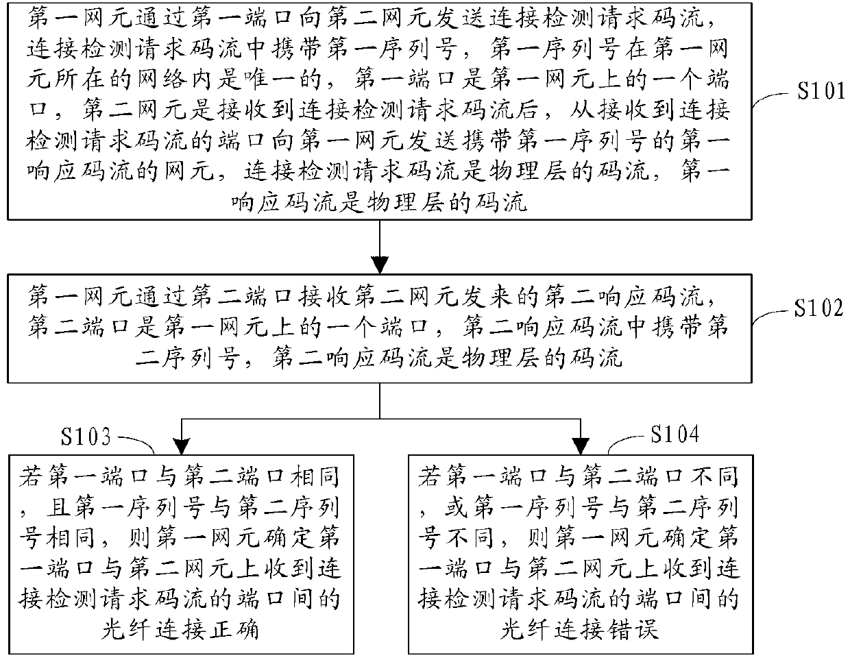
[0058] Such as figure 1 As shown, the embodiment of the present invention provides a method for detecting the connection state of an optical fiber, involving the side of the first network element, and the method may include:

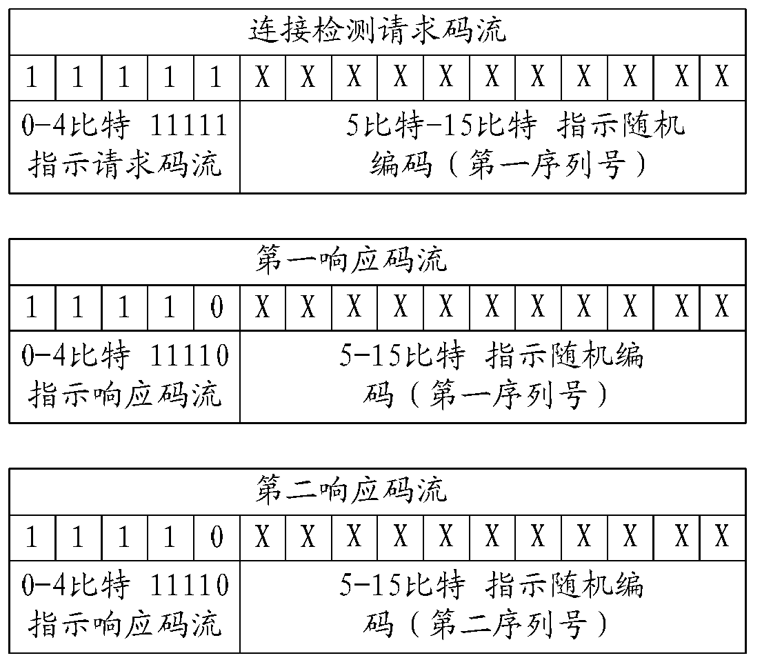
[0059] S101. The first network element sends a connection detection request code stream to the second network element through the first port, the connection detection request code stream carries a first serial number, and the first serial number is unique in the network where the first network element is located , The first port is a port on the first network element, and the second network element receives the connection detection request code stream, and sends the first network element from the port that received the connection detection request code stream to the first network element For the network element of the first response code stream, the connection detection request code stream is a physical layer code stream, and the first response code stream i...

Embodiment 2

[0101] Such as Picture 8 As shown, an embodiment of the present invention provides a network element 1, including:

[0102] The first sending unit 10 is configured to send a connection detection request code stream to a second network element through a first port, the connection detection request code stream carries a first serial number, and the first serial number is located at the network element. Is unique within the network, the first port is a port on the network element, and the second network element is after receiving the connection detection request code stream, from receiving the connection detection request code stream The port that sends the network element of the first response code stream carrying the first serial number to the network element, the connection detection request code stream is a physical layer code stream, and the first response code stream is a physical layer code stream Code stream.

[0103] The first receiving unit 11 is configured to receive a se...

Embodiment 3

[0119] Such as Picture 10 As shown, an embodiment of the present invention provides a network element, including a first transmitter 16, a first receiver 17, a first processor 18, and a first memory 19, where:

[0120] The first transmitter 16 can be used to send signals to other network elements. In particular, if the network element communicates with other network elements, the first transmitter 16 can send communication data to other network elements.

[0121] The first receiver 17 can be used to receive signals from other network elements. In particular, if the network element communicates with other network elements, the first receiver 17 can receive communication data from other network elements.

[0122] The first processor 18 is the control and processing center of the network element. By running the software program stored in the first memory 19, and calling and processing the data stored in the first memory 19, it controls the network element to send and receive signals. ,...


PUM


Abstract

The invention provides an optical fiber connection state detecting method and an optical fiber connection state detecting device and relates to the field of communication. Whether connection among network elements is right or not can be detected so as to improve online efficiency of the network elements and testing efficiency of a network. The method includes the following steps that the first network element sends a connection detecting request code stream to the second network element through a first port and the connection detecting request code stream contains a first serial number. The first network element receives a second responding code stream sent by the second network element through a second port. The second responding code stream contains a second serial number. If the first port is the same as the second port and the first serial number is the same as the second serial number, fiber connection between the first port and the port, receiving the connection detecting request code stream, of the second network element is determined to be right by the first network element.

Description

Technical field [0001] The present invention relates to the field of communication, in particular to a method and device for detecting the connection state of an optical fiber. Background technique [0002] As a mainstream method of broadband access, optical fiber has the advantages of large communication capacity, long relay distance, good security performance, and strong adaptability. Therefore, using optical fiber to access the network has become the development trend of broadband access in the future. [0003] In the optical fiber network construction phase, the staff first install the network elements, and then patch the physical links between the network elements according to the physical connection design drawings. After the optical fiber network construction is completed, the network elements are remotely commissioned to make the network Yuan goes online. Since each port of the network element has two optical fiber interfaces (transmitting interface and receiving interface...

Claims


Application Information

Patent Timeline
IPC IPC(8): H04B10/07
Inventor 袁玉林
Owner HUAWEI TECH CO LTD
Why Eureka
Try Eureka