Cold-rolling strip mill

A cold-rolled strip and rolling mill technology, applied in the direction of metal rolling stands, metal rolling mill stands, metal rolling, etc., can solve the problems of work roll breakage, large bending deformation of work rolls, affecting strip shape, etc. Reliable positioning and large positioning area

Active Publication Date: 2013-10-16
CERI TECH +1
View PDF8 Cites 11 Cited by
  • Summary
  • Abstract
  • Description
  • Claims
  • Application Information

AI Technical Summary

Problems solved by technology

However, due to the structural limitations of the existing four-high and six-high rolling mills, the diameter of the work rolls is large, and it is difficult to roll thinner strips, especially hard-to-deform materials
In order to roll thinner strips and hard-to-deform materials, small-diameter work rolls can be used for rolling; however, during the rolli

Method used


Image

  • Cold-rolling strip mill
  • Cold-rolling strip mill
  • Cold-rolling strip mill

Examples


Embodiment 1

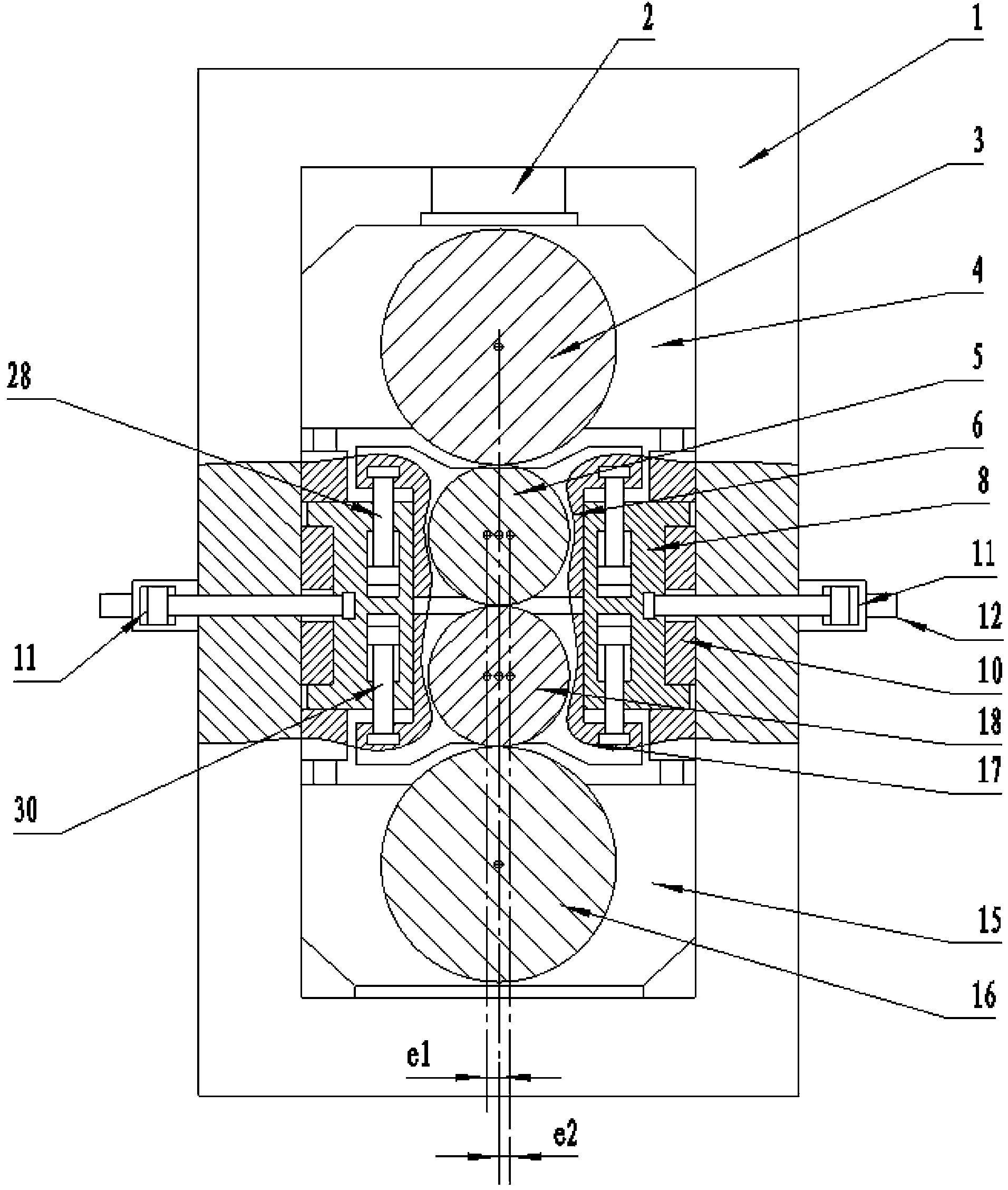
[0025] The cold strip mill of the present invention will be described in detail below in conjunction with the accompanying drawings. Such as figure 1 Shown, a kind of cold-rolled strip rolling mill comprises frame 1, is provided with upper work roll 5 and lower work roll 18 in frame 1, is provided with upper back-up roll 3 above upper work roll 5, and lower work roll 18 The lower support roll 16 is arranged below, and the two ends of the upper work roll 5 are respectively provided with upper work roll bearing housings 6, that is, there are two upper work roll bearing housings 6, and the two ends of the lower work roll 18 are respectively provided with lower work roll bearings. Seat 17, that is, there are 2 lower work roll chocks 17 in total, and the two sides of the upper work roll chock 6 and the lower work roll chock 17 are respectively provided with bending block pedestals 8, that is, there are 4 bending roll chocks 8 in total. There is a gap between the work roll chock 6 ...

Embodiment 2

[0035] This embodiment is an improvement to Embodiment 1, mainly because the upper bending block 7 and the lower bending block 14 are added to the cold strip mill described in the embodiment.

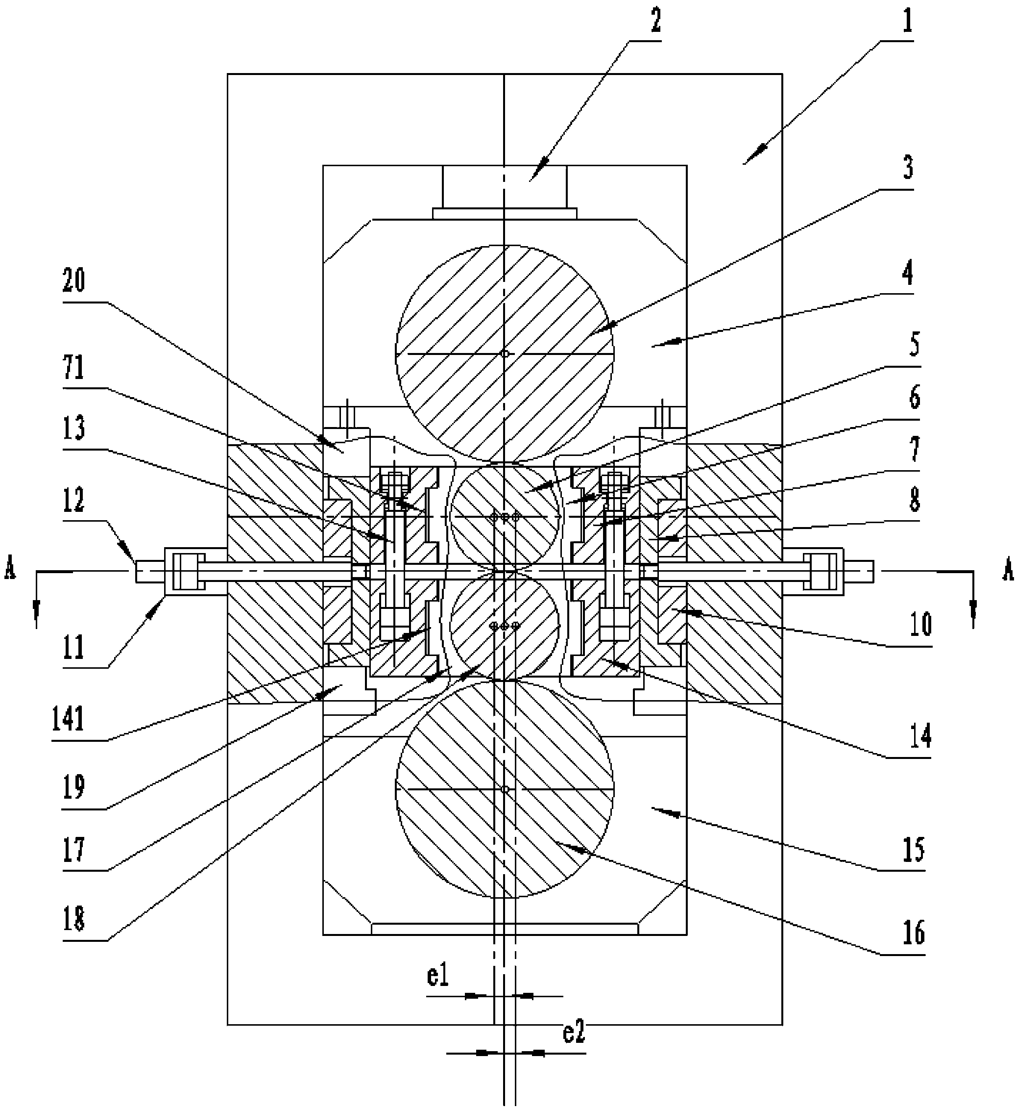
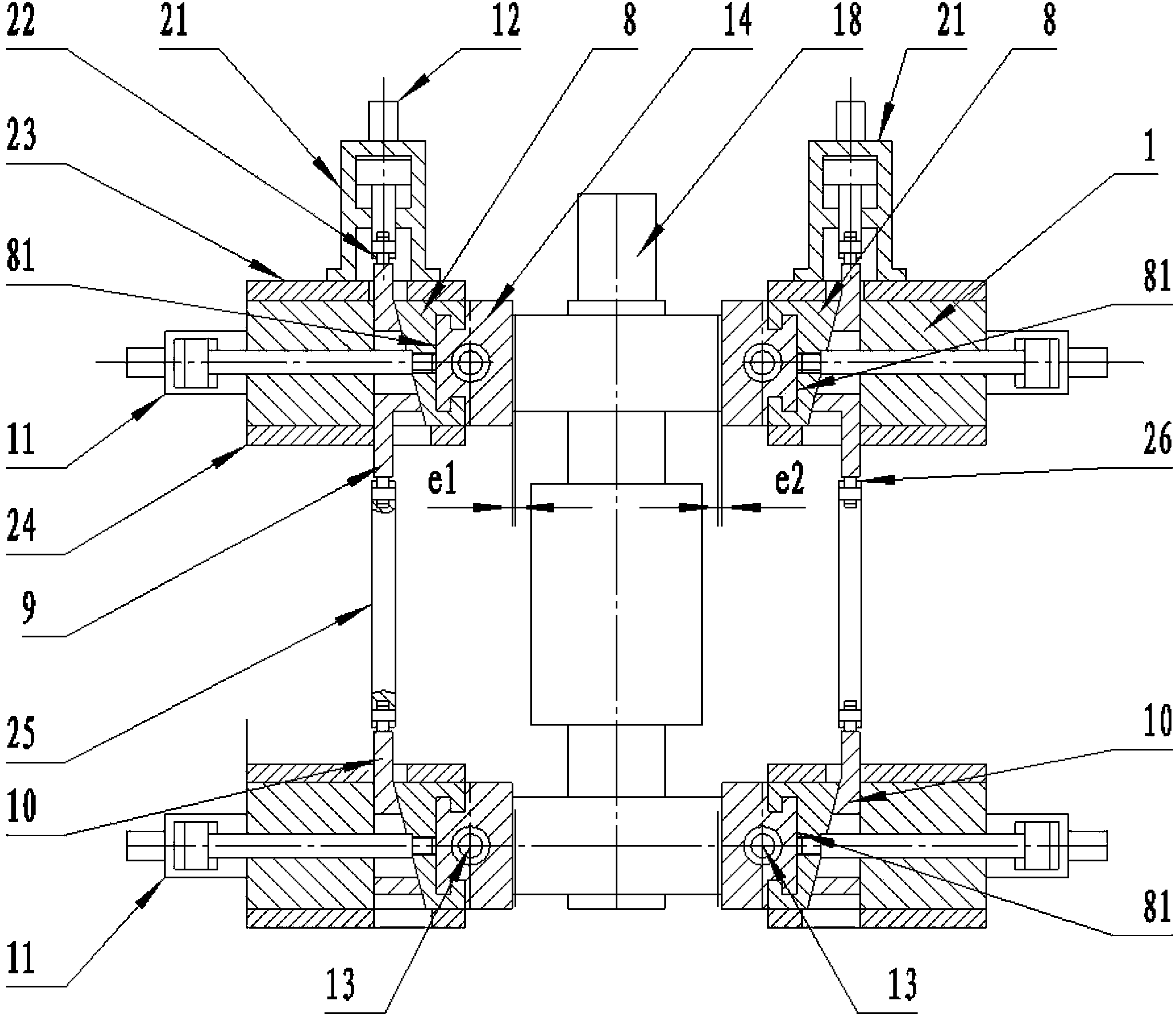
[0036] Specifically, the two sides of the two upper work roll chocks 6 are respectively fixedly connected to the four upper roll bending blocks 7 through four upper bending block blocks 7, and the four upper bending block blocks 7 are provided with the upper work roll chocks 6 The groove 71 that slides along the axial direction of the upper work roll 5, the bending block seat 8 is provided with a T-shaped groove 81 for the upper bending block 7 to slide in the vertical direction; the two sides of the two lower work roll bearing seats 17 respectively pass through The 4 lower bending blocks 14 are fixedly connected with the 4 bending block seats 8, the lower bending block 14 is provided with a groove 141 for the lower work roll bearing housing 17 to slide along the axial direction of the l...

Embodiment 3

[0043] This embodiment is an improvement to Embodiment 1, mainly because the upper bending block 7 and the lower bending block 14 are added to the cold strip mill described in the embodiment.

[0044] Specifically, the two sides of the two upper work roll chocks 6 are fixedly connected to the four bending block seats 8 through four upper bending blocks 7 respectively, and the upper bending blocks 7 are provided with a T The groove 72 and the upper bending block 7 can slide along the direction of the axis of the upper work roll 5; the two sides of the two lower work roll bearing seats 17 are fixedly connected to the four bending block seats 8 through the four lower bending blocks 14 respectively , the lower bending block 14 is provided with a T-shaped groove 142 along the direction of the axis of the lower working roll 18, and the lower bending block 14 can slide along the direction of the axis of the lower working roll 18, such as Figure 4 shown.

[0045] The gap between the...


PUM


Abstract

The invention discloses a cold-rolling strip mill which comprises a rack (1), and an upper back-up roll (3), an upper working roll (5), a lower working roll (18) and a lower back-up roll (16) are sequentially arranged in the rack (1) from top to bottom. The two ends of the upper working roll (5) and the two ends of the lower working roll (18) are provided with upper working roll bearing seats (6) and lower working roll bearing seats (17) respectively, and a bending roll block seat (8) can push the upper working roll bearing seats (6) and the lower working roll bearing seats (17) to move in the horizontal direction vertical to the axis of the upper working roll (17). A horizontal moving cylinder (11) driving the bending roll block seat (8) to move is fixedly connected to the rack (1). The cold-rolling strip mill can horizontally move the upper working roll and the lower working roll in the horizontal direction according to rolling parameters and structure parameters of the strip mill, and therefore the working rollers are stressed to the minimum in the horizontal direction under the condition that the working rollers stably perform rolling.

Description

technical field [0001] The invention relates to the field of metal strip rolling equipment, in particular to a cold strip rolling mill for rolling steel strips, nonferrous metals and alloy strips. Background technique [0002] In the field of cold-rolled steel strip, cold-rolled non-ferrous metal and alloy strip, four-high and six-high rolling mills are widely used to roll wide strips with a width greater than 1000mm. This rolling mill has a complete thickness control and shape control system and corresponding Mechanical structure. However, the existing four-high and six-high rolling mills have large diameters of work rolls due to structural limitations, making it difficult to roll thinner strips, especially difficult-to-deform materials. In order to roll thinner strips and hard-to-deform materials, small-diameter work rolls can be used for rolling; however, during the rolling process of the work rolls, the strip steel exerts a horizontal force on the work roll surface, cau...

Claims


Application Information

Patent Timeline
IPC IPC(8): B21B1/22B21B13/06B21B31/32B21B31/02
Inventor 江东海陈南宁韩志勇胡晓军杨小羽张卫
Owner CERI TECH
Why Eureka
Try Eureka