Auxiliary device for processing of oblique oil hole

A technology of auxiliary device and oblique oil hole, which is applied in the direction of positioning device, metal processing equipment, metal processing machinery parts, etc.

Inactive Publication Date: 2013-10-16
ZHEJIANG GEELY POWERTRAIN CO LTD +2
View PDF6 Cites 3 Cited by
  • Summary
  • Abstract
  • Description
  • Claims
  • Application Information

AI Technical Summary

Problems solved by technology

[0003] When carrying out VVT transformation on the basis of the existing engine, in order to overcome the oblique oil hole of the engine cylinder head in the existing process, offline processing is required, and it needs to be transported back and forth in the middle, and there are many twists and turns However, the present invention provides an auxiliary device for processing oblique oil holes that is relatively simple in structure, easy to use, low in production cost, easy to integrate with existing processes, and can effectively avoid repeated transfers on and off the product line

Method used


Image

  • Auxiliary device for processing of oblique oil hole
  • Auxiliary device for processing of oblique oil hole
  • Auxiliary device for processing of oblique oil hole

Examples


Embodiment 1

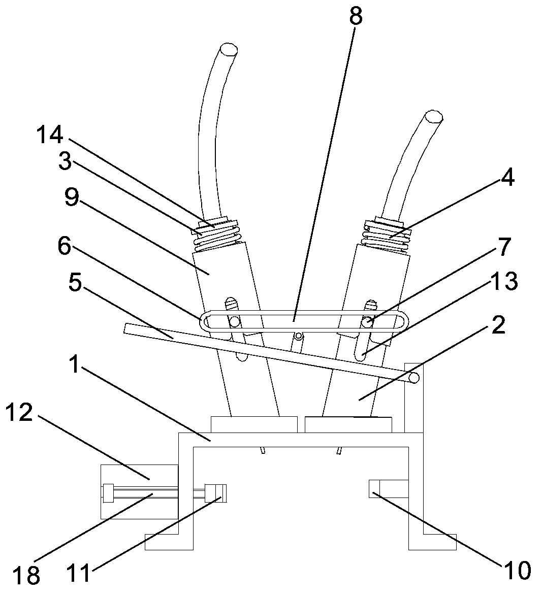
[0025] like figure 1 As shown, an auxiliary device for processing inclined oil holes includes an upper wire support frame 1, a cylindrical drilling tool support sleeve 2, a straight cylindrical drilling tool 3, a return spring 4 and a drilling pressing arm 5, and the drilling tool The support sleeve 2 is obliquely fixed on the upper line support frame 1, and the upper line support frame 1 is provided with a through hole, which communicates with the drilling tool support sleeve 2, and the drilling tool 3 is slidably arranged in the drilling tool support sleeve 2 , the return spring 4 is connected between the drilling tool 3 and the drilling tool support sleeve 2, a linkage mechanism is provided between the drilling tool 3 and the drilling pressing arm 5, and the drilling pressing arm 5 rotates with the upper line support frame 1 through a rotating shaft Connection, the upper line support frame 1 is also provided with a workpiece clamping mechanism. The upper line supp...

Embodiment 2

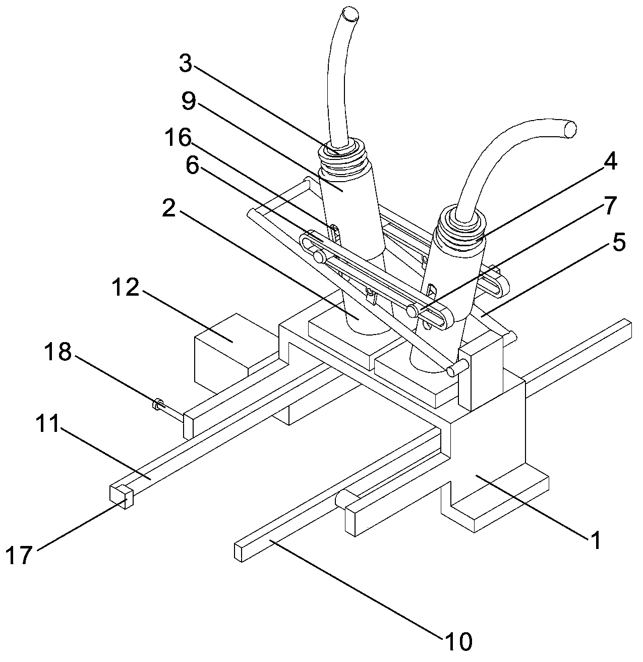
[0028] There are no workpiece arrival sensors and pneumatic stop gauges on the conveying line. One end towards the rear end of the conveying line is provided with a right-angle retaining hook 17 on the moving limit bar 11, such as figure 2 As shown, when the piston rod of the positioning cylinder 12 is retracted, the distance between the end of the right-angle retaining hook 17 and the positioning bar 10 can accommodate the cylinder head workpiece to pass through, and mainly rely on manual positioning of the cylinder head workpiece when the inclined oil hole is processed. During the operation, when the cylinder head workpiece reaches the upper line support frame 1, the operator pushes the cylinder head workpiece to the moving limit bar 11 and makes the side of the cylinder head workpiece close to the moving limit bar 11, and then keeps the cylinder head workpiece and the moving limit bar 11. Push the cylinder head workpiece forward while the position strip 11 is in clos...

Embodiment 3

[0030] Drilling tool 3 is electric drill, all the other are with embodiment 1.

[0031]


PUM


Abstract

The invention discloses an auxiliary device for processing of an oblique oil hole, which comprises an on-line supporting frame, drilling tool supporting sleeves, drilling tools, returning springs and a drilling pressing arm. The drilling tool supporting sleeves are slantingly and fixedly arranged on the on-line supporting frame; the on-line supporting frame is provided with through holes; the through holes are communicated with the insides of the drilling tool supporting sleeves; the drilling tools are arranged in the drilling tool supporting sleeves in a sliding manner; the returning springs connected between the drilling tools and the drilling tool supporting sleeves; a linkage mechanism is arranged between the drilling tools and the drilling pressing arm; the drilling pressing arm is rotationally connected with the on-line supporting frame by a rotating shaft; and the on-line supporting frame is also provided with a workpiece clamping mechanism. The auxiliary device for processing of the oblique oil hole is low in cost, has a simple structure, occupies a small space, is easy to load on line, can be integrated into an existing production line to carry out online drilling processing on an engine cylinder head, avoids a product being moved around, reduces twists and turns and enables drilling processing to be efficient and labor-saving.

Description

technical field [0001] The invention relates to a simple drilling tool, more specifically, it relates to an auxiliary device for processing inclined oil holes. Background technique [0002] In order to reduce the fuel consumption of the engine and improve the overall performance of the engine, it is planned to add a VVT device on the basis of the existing engine, so it is necessary to add an inclined hydraulic oil passage on the wall of the camshaft hole on the front face of the cylinder head to drive VVT device. At present, the main method of processing the hydraulic oil passage on the camshaft hole of the cylinder head of the existing engine is to first complete the size processing of the cylinder head on the existing production line, and then take the cylinder head to other equipment outside the line to carry out the VVT ​​drive oil passage. Drilling processing, after processing, it is transported back to the production line for subsequent processing operations. However...

Claims


Application Information

Patent Timeline
Patent Type & Authority Applications(China)
IPC IPC(8): B23B41/00B23Q3/06B23B47/00
Inventor 黄财明毕家明吕繁伍俊孙艳陈杰王瑞平
Owner ZHEJIANG GEELY POWERTRAIN CO LTD
Why Eureka
Try Eureka