Vertical-type scrap iron scraper conveyor

A scraper and iron filing technology, applied in conveyors, conveyor objects, conveyor control devices, etc., can solve the problems of high manufacturing cost, inconvenient cleaning, and many wearing parts, etc. Easy to clean and simple structure

Inactive Publication Date: 2013-10-16
DALIAN JIALIN EQUIP MFG
View PDF5 Cites 1 Cited by
  • Summary
  • Abstract
  • Description
  • Claims
  • Application Information

AI Technical Summary

Problems solved by technology

[0002] At present, chain-plate conveyors and belt-type conveyors are generally used in domestic and foreign punching machines for scrap iron scrap discharge machines. Chain-plate conveyors are prone to material jams, and the iron filings punched out by punching machines are generally thinner and smaller in area. , it is very easy to drill into the gap of the chain plate, resulting in damage to the chain plate; the belt conveyor is easy to scratch the belt, most of the iron filings punched out by the punching machine have sharp corners, and contain a certain amount of grease, which is very easy to make the iron Chips are tenaciously attached to the surface of the belt and may enter the bottom of the belt and scratch the belt. Therefore, the current domestic and foreign punching machines supporting waste iron scraps discharge vertical iron scrapers generally have a relatively low service life, and the general service life of belt conveyors is half a year to One year; chain-plate conveyors generally have a service life of two to three years. In addition, chain-plate conveyors and belt conveyors are inconvenient to clean, occupy a large area, have high manufacturing costs, and have many wearing parts. Problems such as maintenance difficulties

Method used


Image

  • Vertical-type scrap iron scraper conveyor
  • Vertical-type scrap iron scraper conveyor
  • Vertical-type scrap iron scraper conveyor

Examples


Embodiment Construction

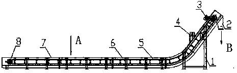
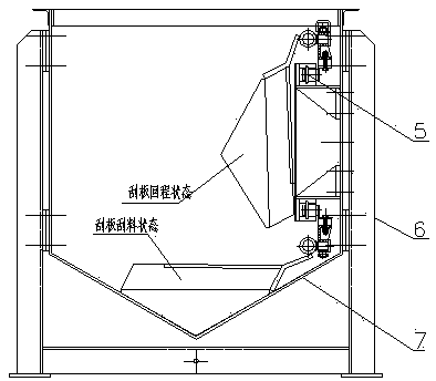
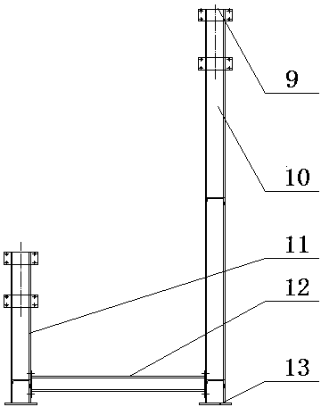
[0028] like Figure 1 to Figure 11 As shown, the vertical iron chip scraper machine includes a high bracket 1, a hopper 2, a main transmission device 3, a lubricating device 4, a scraper device 5, a short bracket 6, a discharge main body 7 and a driven device 8, and a high bracket 1 and the short bracket 6 are respectively connected to the discharge main body 7, the discharge hopper 2 is connected to the discharge main body 7, the main transmission device 3 and the driven device 8 are respectively fixed on both ends of the discharge main body 7, and the lubricating device 4 is fixed on the discharge main body 7. The upper slope of the material body 7 is used to lubricate the chain and prolong the service life of the chain. The scraper device 5 is installed on the material discharge body 7. The high bracket 1 is composed of the first connecting plate 9, the long column 10, and the short column 11. , connecting rod 12, the first anchor plate 13 are welded, and the material of th...


PUM


Abstract

The invention discloses a vertical-type scrap iron scraper conveyor. The vertical-type scrap iron scraper conveyor comprises a high support (1), a discharging hopper (2), a main transmission device (3), a lubricating device (4), a scraping device (5), a short support (6), a discharging body (7) and a passive transmission device (8). The high support (1) and the short support (6) are respectively connected with the discharging body (7), the discharging hopper (2) is connected to the discharging body (7), the main transmission device (3) and the passive transmission device (8) are fixed at the two ends of the discharging body (7) respectively, the lubricating device (4) is fixed on an upper inclined portion of the discharging body (7), and the scraping device (5) is installed on the discharging body (7). The vertical-type scrap iron scraper conveyor is simple in structure, convenient to operate, and solves the problem that a waste scrap iron discharging machine machined by a punch press is short in service life, wherein the service life of the waste scrap iron discharging machine is generally five to eight years. Furthermore, the vertical-type scrap iron scraper conveyor overcomes the defects of being inconvenient to clean, large in occupied area, high in cost, difficult to maintain and the like.

Description

technical field [0001] The invention relates to a vertical iron chip scraper machine. Background technique [0002] At present, chain-plate conveyors and belt-type conveyors are generally used in domestic and foreign punching machines for scrap iron scrap discharge machines. Chain-plate conveyors are prone to material jams, and the iron filings punched out by punching machines are generally thinner and smaller in area. , it is very easy to drill into the gap of the chain plate, resulting in damage to the chain plate; the belt conveyor is easy to scratch the belt, most of the iron filings punched out by the punching machine have sharp corners, and contain a certain amount of grease, which is very easy to make the iron Chips are tenaciously attached to the surface of the belt and may enter the bottom of the belt and scratch the belt. Therefore, the current domestic and foreign punching machines supporting waste iron scraps discharge vertical iron scrapers generally have a rela...

Claims


Application Information

Patent Timeline
Patent Type & Authority Applications(China)
IPC IPC(8): B65G19/04B65G19/20B65G19/22B65G23/24B65G23/44B65G45/02B65G43/08
Inventor 尹柏林刘玉琳
Owner DALIAN JIALIN EQUIP MFG
Why Eureka
Try Eureka