Oil injector oil-return device matched with diesel engine

A fuel injector and diesel engine technology, applied in fuel injection devices, machines/engines, charging systems, etc., can solve problems such as complex cylinder head structure design, high fuel consumption of diesel engines, and poor performance of the main engine, and achieve good promotion and application value. The effect of reducing operating costs and simplifying structural design

Active Publication Date: 2013-10-16
山东科林动力科技有限公司 +1
View PDF6 Cites 4 Cited by
  • Summary
  • Abstract
  • Description
  • Claims
  • Application Information

AI Technical Summary

Problems solved by technology

[0002] In the structure of each part of the diesel engine, the setting of the oil return passage of the injector is very critical. It is necessary to ensure that the oil passage is tightly sealed. If the setting is unreasonable, there will be fuel leakage, leakage, fuel mixed with lubricating oil, etc., which will cause high fuel consumption of the diesel engine. , the discharge does not meet the standard, and the lubrication fails, which leads to poor performance of the main engine, and in severe cases, it will cause major accidents such as damage to the whole machine
The oil return passage of the traditional injector is arranged inside the injector body. After the injector completes one injection, the excess fuel returns to the low-pressure oil circuit through the return passage in the injector body and the oil return connector of the injector. Although this oil return method can realize the oil return of the injector, the structural design of the cylinder head is relatively complicated, and the oil return channel of the injector will interfere with other related components and bring adverse effects

Method used


Image

  • Oil injector oil-return device matched with diesel engine
  • Oil injector oil-return device matched with diesel engine

Examples


Embodiment Construction

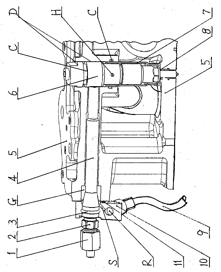
[0009] Specific embodiments of the present invention will be described below in conjunction with the accompanying drawings.

[0010] refer to figure 1 , the cylinder head 5 of the diesel engine is provided with a horizontal high-pressure oil connection installation hole G and a vertical fuel injector installation hole D, the fuel injector 6 is installed in the fuel injector installation hole D, the lower section is equipped with a copper sleeve 7, and the bottom is equipped with a copper sleeve Gasket 8, O-ring sealing ring 3 is embedded in the sealing groove C of the upper part of the fuel injector 6, and the sealing ring 3 is set outside the copper sleeve 7, and the radial sealing groove opened on the inner wall of the fuel injector installation hole D of the cylinder head 5 is embedded C. The high-pressure oil connecting pipe 4 is installed horizontally in the installation hole G of the high-pressure oil connecting pipe, and the front end is connected with the oil inlet ho...


PUM


Abstract

An oil injector oil-return device matched with a diesel engine is characterized in that the middle of an oil injector (6) is covered with a copper sleeve (7); the lower part of the oil injector (6) is sleeved with a copper gasket (8); the oil injector (6) is vertically mounted in an oil injector mounting hole (D) of a cylinder cover (5); a high-pressure oil connecting pipe (4) is horizontally mounted in a high-pressure oil connecting pipe mounting hole (G) of the cylinder cover (5); the front end of the high-pressure oil connecting pipe (4) is connected with an oil inlet hole of the oil injector (6); the rear end of the high-pressure oil connecting pipe (4) extends out of the cylinder cover (5) to be connected with a three-way connector (10); the oil injector mounting hole (D) and the high-pressure oil connecting pipe mounting hole (G) form an oil return cavity in the cylinder cover (5). Injected fuel oil flows out from an oil return opening (H) of the oil injector (6) and enters the oil return cavity, flows into the three-way connector (10) through a three-way oil return opening (S) and then flows back to an oil tank through a fuel oil outlet (R) and an oil pipe (9). The structural design of the cylinder cover (5) is simplified, the function of the high-pressure oil connecting pipe mounting hole (G) is expanded, the interference of the oil return passage of the oil injector (6) with other components is reduced, the manufacturing and mounting are easy, failures are reduced and the performance of the main engine is guaranteed.

Description

technical field [0001] The invention relates to a matching mechanism of a diesel engine, in particular to an oil return device for a fuel injector of a diesel engine. Background technique [0002] In the structure of each part of the diesel engine, the setting of the oil return passage of the injector is very critical. It is necessary to ensure that the oil passage is tightly sealed. If the setting is unreasonable, there will be fuel leakage, leakage, fuel mixed with lubricating oil, etc., which will cause high fuel consumption of the diesel engine. , the discharge does not meet the standard, and the lubrication fails, which leads to poor performance of the main engine, and in severe cases, it will cause major accidents such as damage to the whole machine. The oil return passage of the traditional injector is arranged inside the injector body. After the injector completes one injection, the excess fuel returns to the low-pressure oil circuit through the return passage in th...

Claims


Application Information

Patent Timeline
Patent Type & Authority Applications(China)
IPC IPC(8): F02M61/16
Inventor 乌江史永康周明张卫军张明杨旎付立昌张秉鉴黄金鹏
Owner 山东科林动力科技有限公司
Why Eureka
Try Eureka