Hall element testing apparatus

A Hall element and testing device technology, applied in the direction of instruments, etc., can solve the problems of troublesome measurement, low efficiency, and low accuracy, and achieve the effects of improving testing efficiency, convenient use, and avoiding repeated disassembly and assembly of wires

Inactive Publication Date: 2013-10-16
STATE GRID CORP OF CHINA +2
View PDF9 Cites 2 Cited by
  • Summary
  • Abstract
  • Description
  • Claims
  • Application Information

AI Technical Summary

Problems solved by technology

In the prior art, the test is carried out manually. During the test, a wire is used to pass through a Hall element to be tested on the Hall board, and then the two ends of the wire are connected to the test instrument to load the current. After the test is completed, the test is carried out. For the next Hall element, since the wire needs to pass through the Hall element for each test, it needs to be repeatedly disassembled and wired, which is cumbersome to measure, low in efficiency, and divided loading cannot guarantee the current intensity of each time, and there is a current deviation , the accuracy is not high

Method used


Image

  • Hall element testing apparatus
  • Hall element testing apparatus

Examples


Embodiment Construction

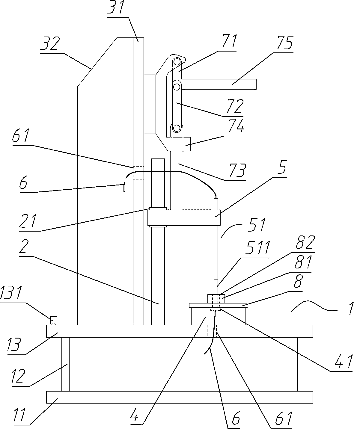
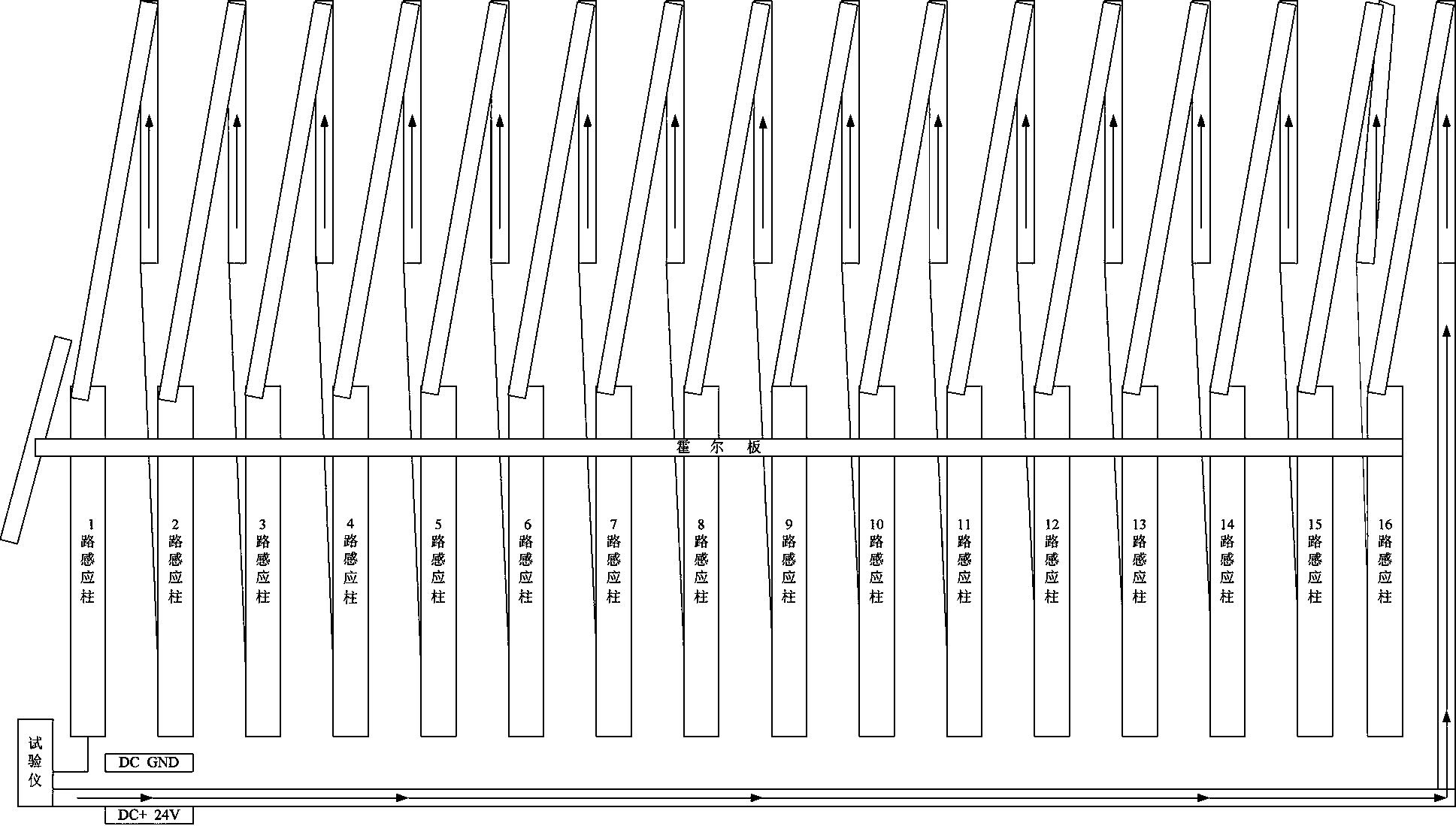
[0015] An embodiment of the Hall element testing device of the present invention is as Figure 1~Figure 2 As shown, it is used to test the Hall plate 8 with sixteen Hall elements 81 arranged in the same line, including a device frame, which includes a horizontally arranged base plate 1 and a vertical plate 31 perpendicular to the base plate 1; wherein The bottom plate 1 includes a bottom working plate 13 and a base plate 11. The four corners of the base plate 11 are provided with pillars 12 to support the bottom working plate 13 to form an isolated space, which is convenient for the laying and hiding of the wires 6, making the whole more concise and beautiful; Ribs 32 are connected to the side, which can ensure the overall stability of the device frame.

[0016] The Hall element testing device also includes a moving contact seat 5 and a static contact seat 4 made of insulating and transparent acrylic material. The bottom working plate 13 is provided with a guide column 2 exte...


PUM


Abstract

The invention relates to a Hall element testing apparatus. The apparatus comprises a frame, a moving contact seat assembled on the frame and movable under guide along a preset guide direction, and a fixed contact seat fixed on the frame. The moving contact seat is provided with a conductive post extending along the guide direction of the moving contact, and the conductive post has a conductive terminal passing though a corresponding bore of a Hall element. The fixed contact seat is provided with a fixed contact corresponding to the conductive terminal in the guide moving direction of the moving contact seat. In the guide moving path of the moving contact seat, a connecting position is provided by which the conductive post is driven to pass through the corresponding bore of the Hall element and conductively connected with the fixed contact; and a separating position is also provided by which the conductive post is pulled out of the corresponding bore of the Hall element. The conductive post and the fixed contact each has a conductive terminal for receiving a corresponding current generated by the testing apparatus. The apparatus can be used for testing the Hall element with convenience.

Description

technical field [0001] The invention relates to a Hall element testing device. Background technique [0002] The Hall element is a magnetic sensor based on the Hall effect. It can detect the magnetic field and its changes. It can be used in various occasions related to the magnetic field. It will be measured such as current, magnetic field, displacement, angle, speed, pressure, etc. converted into an electrical signal output. For example, an existing Hall plate includes a printed circuit board and a plurality of Hall elements arranged side by side on the printed circuit board. Corresponding to the connected through hole, when a current passes through the through hole on the Hall element, the Hall element can detect the corresponding magnetic field and output a corresponding electrical signal. [0003] In order to ensure the accuracy of the Hall element, each Hall element on the Hall board needs to be tested, such as offset calibration and gain calibration, etc., which requ...

Claims


Application Information

Patent Timeline
IPC IPC(8): G01D18/00
Inventor 张举良马仪成焦丽娜郭改霞张雅王献奎王萌张聪
Owner STATE GRID CORP OF CHINA
Why Eureka
Try Eureka