A separate photoelectric control device that can be installed separately

A photoelectric control, separate technology, applied in the direction of measuring device, lubrication indicating device, engine lubrication, etc., can solve the problems of consuming the material to be measured, increasing the installation time and material cost, and poor system identification.

Inactive Publication Date: 2015-11-18
上海凡宜科技电子有限公司
View PDF5 Cites 0 Cited by
  • Summary
  • Abstract
  • Description
  • Claims
  • Application Information

AI Technical Summary

Problems solved by technology

[0004] Under normal circumstances, the above-mentioned conventional technology can only correctly output the state of measuring whether the object under test actually exists or does not exist. However, this circuit has a disadvantage. After the installation of the measuring device is completed, the user usually wants to perform the system first Testing, at this time, it is necessary to actually change the appearance state of the object under test before the overall system test can be carried out. However, in actual applications, it is not so easy and convenient to control the appearance of the object under test, and it may take a long time. It may even need to consume the material to be tested, which will increase the installation time and material cost
[0005] Currently existing technologies U.S.Pat.No.4,201,914 and U.S.Pat.No.4,134,022 can only perform analog alarms at the high position of the barrel tank; and in U.S.Pat.No.4,354,180, such as figure 2 , although both high and low bits can output alarms, the method used is to use a state electrical signal for the sensed signal, whether it is high or low, and then use this signal to output an alarm. The disadvantage of this method is the degree of system recognition. Poor, and can only be used for known solutions, if the solution to be tested is not the solution in the system design, there may be malfunctions

Method used


Image

  • A separate photoelectric control device that can be installed separately
  • A separate photoelectric control device that can be installed separately
  • A separate photoelectric control device that can be installed separately

Examples


Embodiment 1

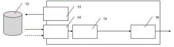
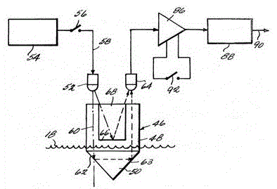
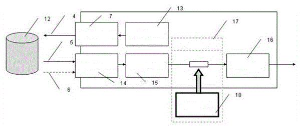
[0033] Such as image 3 Shown is an embodiment of the present invention, wherein the signal processing unit includes a light emitting module 13 , a light receiving module 14 , a signal processing module 15 , and an output circuit module 16 . The above-mentioned light emitting module 13 emits a light signal 4, and the light source passes through a light modulating device 7, which can change the intensity, phase, and luminous field type of light, and other characteristics. When there is no object 12 under test, the light signal 5 will be fed back to light receiving module 14; otherwise, no light signal will return to the light receiving module 14. The signal of the light receiving module 14 will be delivered to the signal processing module 15, and after the signal is processed, it will pass through the analog test unit 17, refer to Figure 4 , which includes an additional trigger signal 18 that can control a switch 22, the switch can be a single-pole double-throw (SinglePoleDou...


PUM


Abstract

The invention discloses a separated type photoelectric control device capable of being installed in a separating mode. The separated type photoelectric control device is used for measuring a material level and a liquid level and comprises an optical detecting head and a signal processing unit. The optical detecting head is separably connected with the signal processing unit and can judge the locking state or the separating state of the optical detecting head and the signal processing unit. The signal processing unit comprises a light emitting module, a light receiving module, a signal processing module and a signal outputting module. An optical path of a light signal is changed by an object to be detected, and the light signal is sent to the light receiving module. The light receiving module sends the light signal to the signal processing module, the signal processing module analyzes and processes the light signal so as to obtain an output signal and send the output signal to the signal output module, and the output signal is outputted. According to the separated type photoelectric control device capable of being installed in the separating mode, the state of the object to be detected does not need to be changed and outputting of various simulation alarm signals can be performed; meanwhile, locking or separating of the optical detecting head and the signal processing unit can be judged.

Description

technical field [0001] The invention relates to the field of photoelectric control, in particular to a detachably installed separated photoelectric control device. Background technique [0002] The operating principle of the existing photoelectric switch measuring device is as follows: figure 1 As shown, it includes an optical transmitter (13), an optical receiver (14), a signal processing unit (15), and a signal output circuit (16). [0003] When the object to be measured does not exist and the object to be measured appears, there will be two different light receiving states, one is that the light receiver has received a signal, or has not received a signal. After signal processing, the transformation of the signal can treat the photoelectric measuring device as a switch device for controlling other back-end equipment. [0004] Under normal circumstances, the above-mentioned conventional technology can only correctly output the state of measuring whether the object under ...

Claims


Application Information

Patent Timeline
Patent Type & Authority Patents(China)
IPC IPC(8): G01F23/292
Inventor 吴定国
Owner 上海凡宜科技电子有限公司
Why Eureka
Try Eureka