
Impedance protection method and apparatus suitable for micro-electrical network

An impedance protection and microgrid technology, applied in emergency protection circuit devices, electrical components, etc., can solve the problem that the relay protection method cannot meet the requirements of the microgrid, and achieve the effect of rapid isolation and clear selectivity

Inactive Publication Date: 2013-10-16
STATE GRID CORP OF CHINA +1
View PDF4 Cites 11 Cited by
  • Summary
  • Abstract
  • Description
  • Claims
  • Application Information

AI Technical Summary

Problems solved by technology

[0007] The purpose of the present invention is to provide an impedance protection method and device suitable for micro-grids to solve the problem that existing relay protection methods cannot meet the requirements of micro-grids

Method used

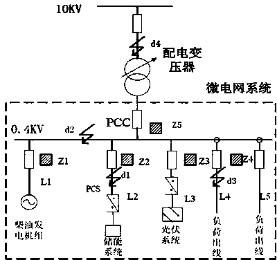
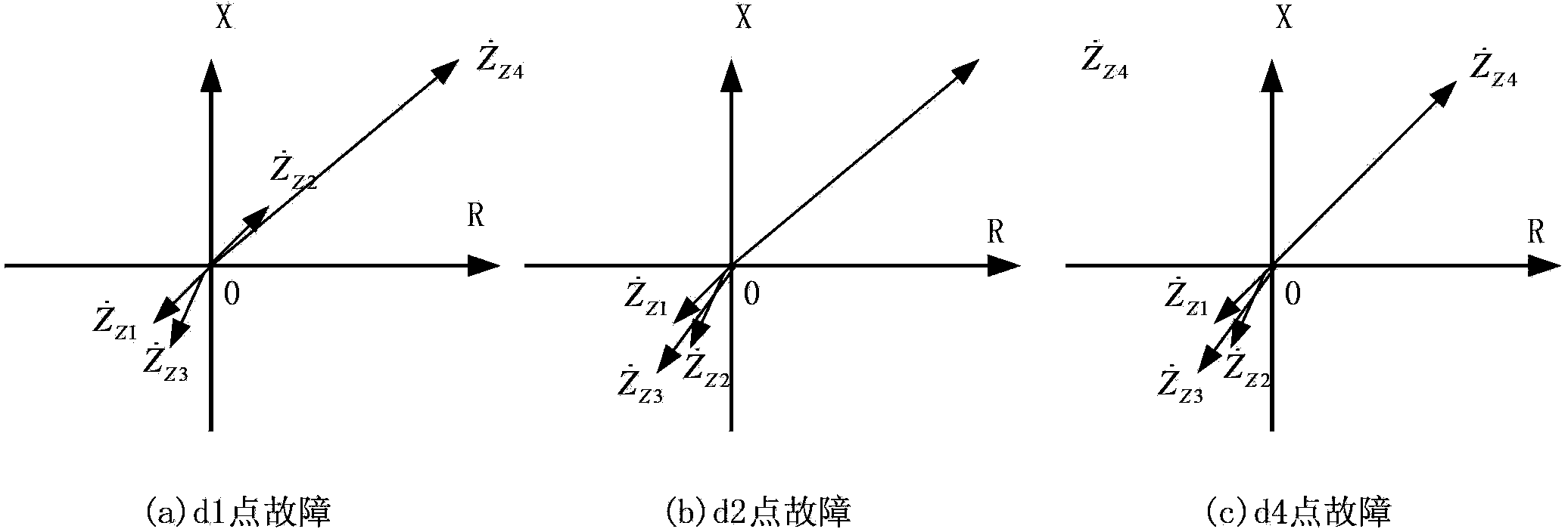

Image

  • Impedance protection method and apparatus suitable for micro-electrical network
  • Impedance protection method and apparatus suitable for micro-electrical network
  • Impedance protection method and apparatus suitable for micro-electrical network

Examples


Embodiment approach

[0042] As an implementation mode, an overcurrent starting element is used, and the criterion is:

[0043] |I φ |>|I ZD or | I φφ | > 3 | * I ZD - - - ( 1 )

[0044] In the formula: is the phase-to-phase current, is the phase current, I ZD is the overcurrent setting.

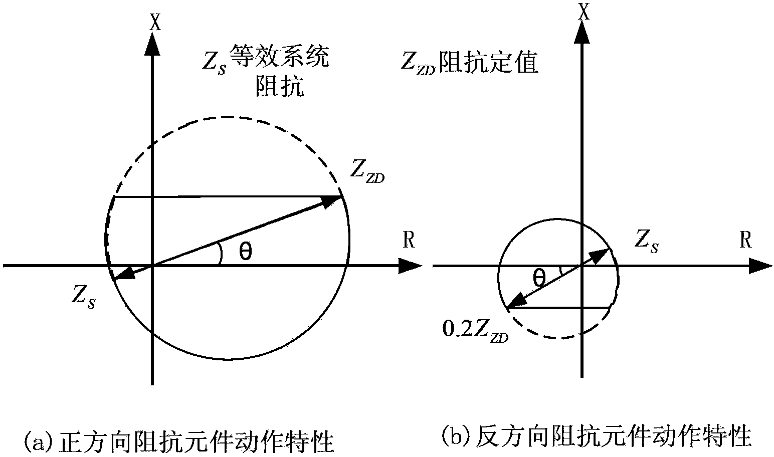
[0045] Criterion of positive direction impedance element:

[0046] and|X m |ZD *Sinθ| (2)

[0047] Equation (2) adopts positive sequence memory voltage polarization, which has clear directionality; where is the positive sequence memory voltage between phases, is the phase-to-phase voltage, is the current between phases, Z set is the fixed value of impedance, X m To measure the reactance, θ is the impedance angle, Z ZD Set a value for impedance.

[0048] Reverse direction impedan...


PUM


Abstract

The invention relates to an impedance protection method and an apparatus suitable for a micro-electrical network. Based on obvious voltage reduction when faults appear in the micro-electrical network and clear directivity of impedance protection, rapid isolation of the faults is realized by protective apparatuses oppositely configured in on-site and dispersed manners.

Description

technical field [0001] The invention relates to the field of relay protection, in particular to an impedance protection method and device suitable for microgrids. Background technique [0002] The transformation of the traditional power network to the smart grid will become a new direction of power grid transformation in the 21st century. In the smart grid, the smart microgrid is gradually gaining the favor of countries all over the world because it can utilize green and clean energy, can be distributed near users to improve the reliability of power supply at the load side, and can realize energy cascade utilization, energy saving, environmental protection, and high energy utilization efficiency. . [0003] Microgrid is a small-scale decentralized independent system. It adopts a large number of modern power technologies, combines gas turbines, wind power, photovoltaic power generation, fuel cells, energy storage equipment, etc., and directly connects to the user side. The ...

Claims


Application Information

Patent Timeline
Patent Type & Authority Applications(China)
IPC IPC(8): H02H7/26H02H7/22
Inventor 李富生雷振锋李瑞生杨恢宏唐云龙王若醒路进升刘桂莲
Owner STATE GRID CORP OF CHINA
Learn More