
DC power grid line fault protection method

A technology of direct current transmission lines and direct current power grids, which is applied in the direction of circuit devices, emergency protection circuit devices, electrical components, etc., can solve the problems of long communication delay of arbitration unit, long communication delay, unfavorable fast fault location, etc., and achieve fast The effect of isolating and reducing the effects of stability

Active Publication Date: 2017-07-07
GLOBAL ENERGY INTERCONNECTION RES INST CO LTD +2
View PDF4 Cites 18 Cited by
  • Summary
  • Abstract
  • Description
  • Claims
  • Application Information

AI Technical Summary

Problems solved by technology

However, this method is based on the premise that the wave impedance of the grid branches is the same, ignoring the influence of wave velocity on the detection of traveling waves; in addition, this method still needs to compare the arrival time of traveling waves at each converter station, and there is still an arbitration unit and a long time communication delay; finally, with the complexity of DC system line structure, the applicability of this method needs further verification
[0009] The deficiencies of existing DC power grid line fault protection methods can be summarized into two points: first, there is a long communication delay, which is not conducive to the realization of fast fault location; second, the implementation method cannot be applied to large-scale DC power grids protection application needs

Method used


Image

  • DC power grid line fault protection method
  • DC power grid line fault protection method

Examples


Embodiment Construction

[0036] The specific implementation manners of the present invention will be further described in detail below in conjunction with the accompanying drawings.

[0037] The following description and drawings illustrate specific embodiments of the invention sufficiently to enable those skilled in the art to practice them. Other embodiments may incorporate structural, logical, electrical, process, and other changes. The examples merely represent possible variations. Individual components and functions are optional unless explicitly required, and the order of operations may vary. Portions and features of some embodiments may be included in or substituted for those of other embodiments. The scope of embodiments of the present invention includes the full scope of the claims, and all available equivalents of the claims. These embodiments of the present invention may be referred to herein, individually or collectively, by the term "invention", which is for convenience only and is not...


PUM


Abstract

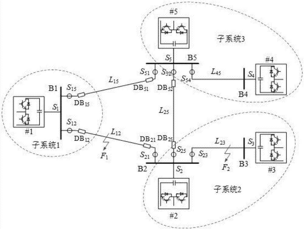
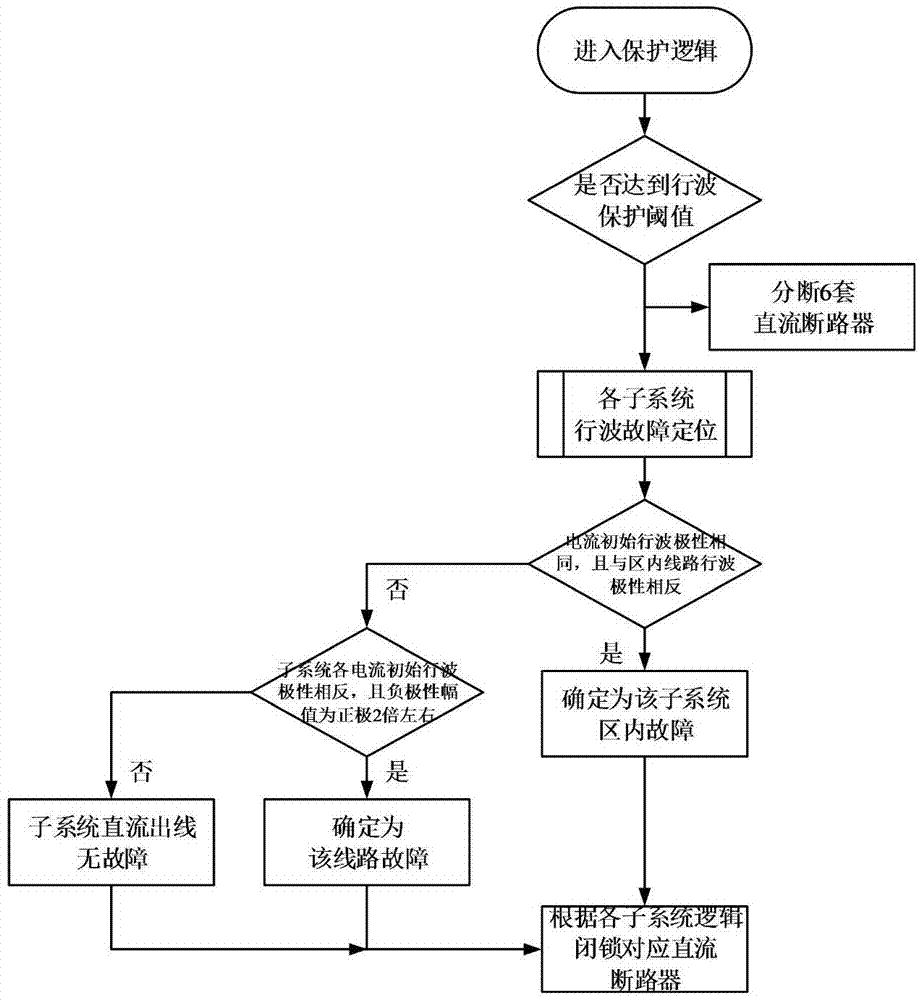
The invention relates to a DC power grid line fault protection method. The method comprises steps: travelling wave signals at each measurement point are monitored in real time, if a protected set threshold is reached, a corresponding DC circuit breaker is tripped, all circuit breakers are finally tripped to realize separation of three DC subsystems, and the control mode of each subsystem converter station is switched. According to the travelling waves acquired at the measurement point, whether the fault is subsystem internal fault or subsystem external fault is judged by each subsystem through a fault positioning logic. If the subsystem external fault is judged according to the fault positioning logic, the line of the fault is determined according to the fault positioning logic, or otherwise, the subsystem internal fault is judged. According to an instruction of a dispatching system, the control mode of each converter station and a power control instruction are changed. The technical scheme of the invention can effectively shorten time needed for fault positioning, and power transfer brought by large-range DC power grid locking and influences on the stability of an AC and DC system can be reduced as much as possible. The phenomenon that the disclosed method is not applicable along with complexity of the DC power grid structure does not happen.

Description

technical field [0001] The invention relates to a fault protection method for a direct current power grid technology of a power system, in particular to a fault protection method for a direct current power grid line. Background technique [0002] The DC power grid is an energy transmission system composed of a large number of DC terminals interconnected in the form of DC. The International Conference on Large Power Grids (CIGRE) defines the DC power grid as: a DC network composed of multiple meshed and radially connected converters. An important platform for implementing new energy strategies and optimizing the allocation of energy resources. It covers power transmission, power transformation, power distribution and other links. Using advanced direct current transmission technology, it can realize large-scale renewable energy power generation access technology and large-capacity long-term Long-distance transmission, improve energy utilization efficiency, and ensure safe, rel...

Claims


Application Information

Patent Timeline
Patent Type & Authority Applications(China)
IPC IPC(8): H02H7/26H02H1/00
CPCH02H1/0007H02H7/265H02H7/268
Inventor 贺之渊孔明吴亚楠杨杰庞辉阎发友
Owner GLOBAL ENERGY INTERCONNECTION RES INST CO LTD
Learn More