Method for converting drilling and milling functions of deep hole drilling machine conveniently

A deep hole drilling machine, drilling and milling technology, applied to other manufacturing equipment/tools, large fixed members, metal processing machinery parts, etc., can solve the problems of different structure of the front guide box, affect the accuracy, low efficiency, etc., to save manpower and operating time, increased service life, and high degree of automation

Active Publication Date: 2013-10-23
太仓吉井机械有限公司
View PDF4 Cites 3 Cited by
  • Summary
  • Abstract
  • Description
  • Claims
  • Application Information

AI Technical Summary

Problems solved by technology

Because the front guide box has a certain width, the spindle must be made very long, which affects the cutting efficiency and machine tool accuracy;
[0004] 2. The structure of the front guide box of the gun drill, single-tube drill, and ejector drill is different. In order to be interchangeable, the front guide box is made very complicated, but even this is not effective and affects the accuracy of each other;
[0005] 3. An additional milling attachment is added, but it is not widely used due to the trouble of clamping
[0006] To sum up, the existing drilling and milling exchange methods used in the machining of workpieces all have technical deficiencies, such as troublesome operation, low precision, low efficiency, and the status of only one as the main and the other as the auxiliary cannot be broken through. However, the same machine tool cannot function normally on gun drilling, single tube drilling, ejector drilling and milling

Method used


Image

  • Method for converting drilling and milling functions of deep hole drilling machine conveniently
  • Method for converting drilling and milling functions of deep hole drilling machine conveniently
  • Method for converting drilling and milling functions of deep hole drilling machine conveniently

Examples


Embodiment Construction

[0031] In order to make the object, technical solution and advantages of the present invention clearer, the present invention will be further described in detail below in conjunction with the accompanying drawings and embodiments. It should be understood that the specific embodiments described here are only used to explain the present invention, not to limit the present invention.

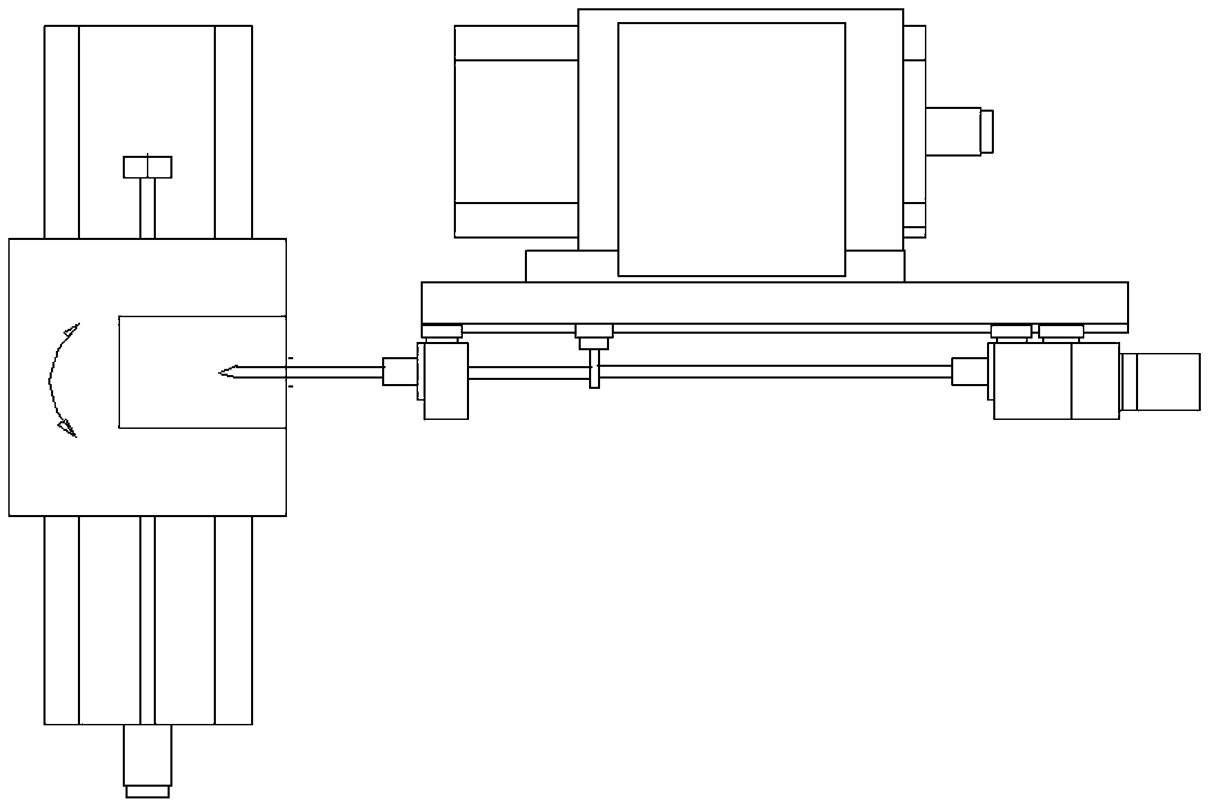
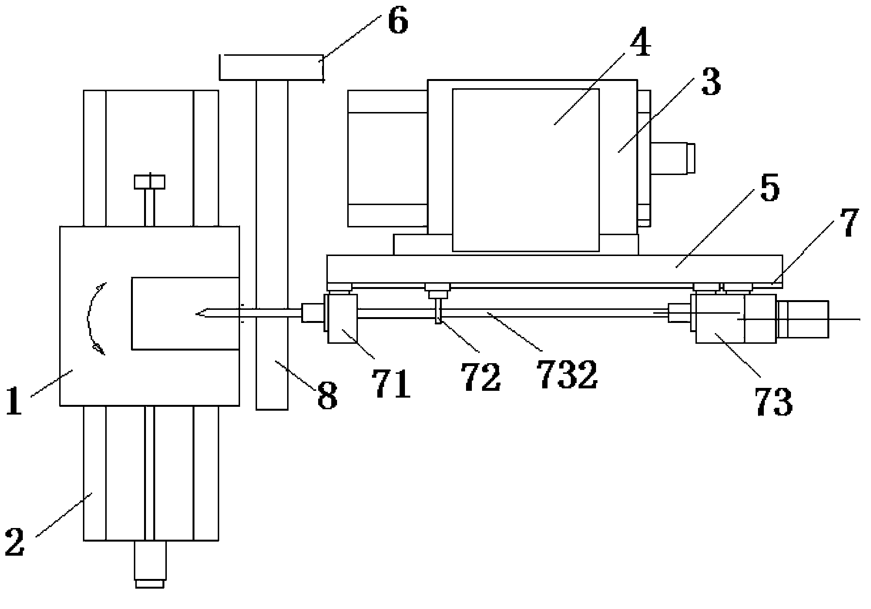
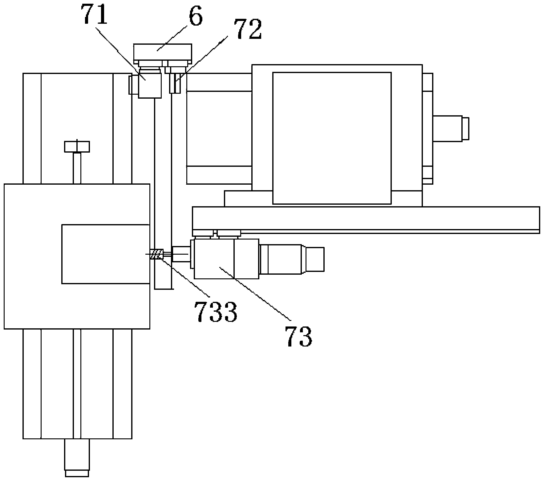
[0032] The method for conveniently switching the drilling and milling functions of the deep hole drilling machine provided by the present invention introduces a drilling and milling exchange mechanism, and the drilling and milling exchange mechanism is provided with a placement guide rail that can be docked with the sliding plate guide rail. When drilling and milling is exchanged, the drilling and milling exchange mechanism Move to one end of the slide guide rail, and the installation guide rail of the drilling and milling exchange mechanism is docked with the slide guide rail. When deep drilling is...


PUM


Abstract

The invention provides a method for converting drilling and milling functions of a deep hole drilling machine conveniently, and provides a drilling and milling converting mechanism. The drilling and milling converting mechanism moves to one end of a slide plate guide rail; a placing guide rail of the drilling and milling converting mechanism is butted with the slide plate guide rail; a front guiding box and a support rack are transferred to the placing guide rail from the slide plate guide rail, or transferred to the slide plate guide rail from the placing guide rail; the drilling and milling converting mechanism is removed after transferring is fulfilled. Through the adoption of the drilling and milling converting mechanism, the Z-axis structure mode of the conventional drilling and milling machine tool is broken through, the front guiding box and the support rack can be transferred freely, the operation of demounting the front guiding box and the support rack is eliminated, precision impact is avoided, and the service life is prolonged.

Description

technical field [0001] The invention relates to the field of drilling and milling of workpieces, in particular to a method for conveniently switching the drilling and milling functions of a deep hole drilling machine. Background technique [0002] In the existing technology, it is very troublesome to realize the structure of drilling, milling exchange and multi-purpose (gun drill, single-tube drill, spray suction drill), and the precision is not high, and they affect each other. Most of them are realized by deep hole drilling and milling machines. . like figure 1 As shown, in order to adapt to deep hole processing, the existing deep hole drilling and milling machine tool has a very long gun drill, which requires a front guide box and several support frames. When performing deep hole drilling and milling interchange, the gun drill needs to be longer And thin can meet the needs of deep hole processing, and because of the large working torque during milling, shorter and thick...

Claims


Application Information

Patent Timeline
IPC IPC(8): B23P23/02B23Q1/72
Inventor 孙燕晶赵俊凤
Owner 太仓吉井机械有限公司
Why Eureka
Try Eureka