Prestress assembly frame structure

A frame structure, prestressed technology, applied in the direction of building structure, construction, etc., can solve the problem of ineffective energy consumption of beam-column joints and column base joints, inability to protect concrete in the interface compression zone, and inconvenient realization of column-column joints To achieve the sustainable development of social economy, improve the level of industrialization of construction, and improve the effect of earthquake resistance

Inactive Publication Date: 2013-10-23
CHINA UNIV OF MINING & TECH
View PDF5 Cites 37 Cited by
  • Summary
  • Abstract
  • Description
  • Claims
  • Application Information

AI Technical Summary

Problems solved by technology

[0010] Purpose of the invention: In order to overcome the deficiencies in the prior art, the present invention provides a prestressed assembly frame structure, which solves the problem that the beam-column joints and column base joints in the existing prestressed assembly frame structure cannot effectively consume energy under a large earthquake, It is impossible to provide compression protection for the concrete in the interface compression area, and the beam distribution method is unreasonable. At the same time, it also solves the problem of inconvenient realization of column-column joints and the formation of shear weak parts on the connection interface.

Method used


Image

  • Prestress assembly frame structure
  • Prestress assembly frame structure
  • Prestress assembly frame structure

Examples


Embodiment 1

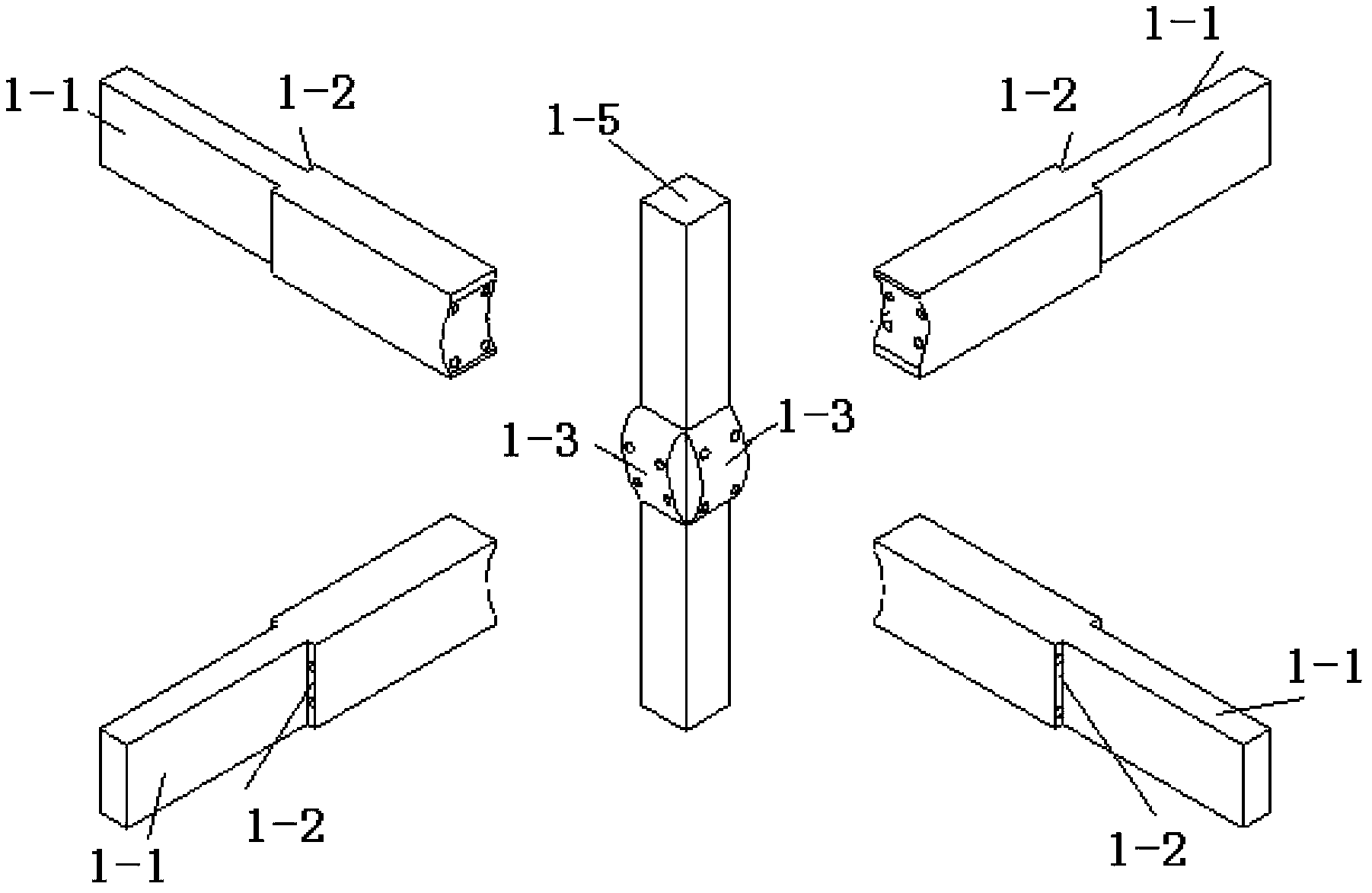
[0036] Embodiment one: if image 3 and 4Shown: When the end face of the side wall raised step 1-2 is wide enough to directly arrange the anchorage and tensioning equipment, in the direction of each main axis of the beam-column connection, the channels and floors in the curved corbel 1-3 The holes in the columns 1-5 and the holes in the floor beam 1-1 are in the shape of two straight lines, the cross-sectional area of ​​the holes at the connection interface is larger than the cross-sectional area of ​​the end of the holes, and the four straight-line holes are connected with the floor beams. The central axis of 1-1 is parallel, and the central axis is the symmetrical central line of the four channels.

Embodiment 2

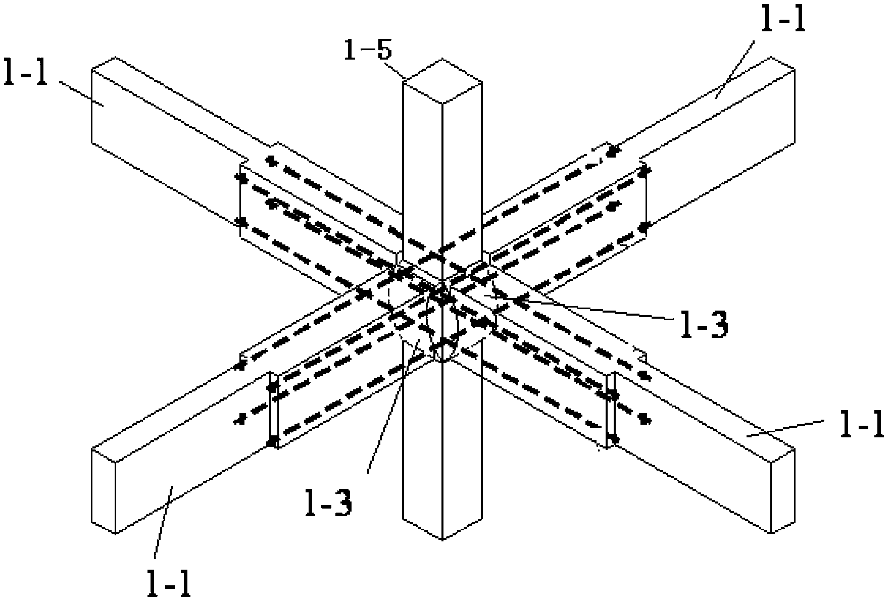
[0037] Embodiment two: if Figure 5 and 6 Shown: When the end face of the side wall raised step 1-2 is narrow enough to directly arrange the anchorage and tensioning equipment, in the direction of each main axis of the beam-column connection, the holes in the curved corbel 1-3, The tunnels in the floor columns 1-5 and the tunnels in the floor beams 1-1 are in the shape of two curves, the cross-sectional area of ​​the tunnels at the connection interface is larger than the cross-sectional area of ​​the tunnel ends, and the four curved tunnels are along the floor. The central axis of the beam 1-1 is symmetrical to the center, and the tunnel in the floor beam 1-1 enters obliquely from the end surface of the raised step 1-2 on the side wall.

[0038] In the above-mentioned beam-column joints, when the floor column 1-5 is a central column, the side walls of the floor column 1-5 are provided with floor beams 1-1; when it is a side column, the three floor columns 1-5 The side walls ...


PUM


Abstract

The invention discloses a prestress assembly frame structure which comprises floor beams, a floor post and a foundation, wherein the floor post is formed by connecting a plurality of floor post units in sequence from top to bottom, one floor post unit connected with the floor beams is a top post, one floor post unit connected with the foundation is a bottom post, a connecting point between the top post and the floor beams is a beam-post node, a connecting point between two adjacent floor post units is a post-post node, and the connecting point between the bottom post and the foundation is a post-foundation node. Through the improvement on the beam-post node, the post-post node and the post-foundation node, the problems that in a conventional prestress assembly frame structure, the beam-post node and the post-foundation node cannot consume energy effectively under major earthquake, and cannot provide pressed protection for concrete on a pressed area of an interface, and the tendon distribution method is unreasonable are solved, and meanwhile, the problems that the post-post node is inconvenient to accomplish, and an anti-shearing weak part is formed on a connection interface are solved.

Description

technical field [0001] The invention relates to a prestressed assembly frame structure in the field of construction engineering. Background technique [0002] The construction industry is the most primitive but also the most persistent and endless project of human activities, and it has long been one of the most important positions for human beings to consume resources and destroy the environment. The basic way to solve this problem is to implement the industrialization of buildings characterized by factory prefabrication and site assembly. [0003] Worldwide, construction industrialization technology has gone through hundreds of years, and a variety of prefabricated assembly structural systems with continuous technological advancement (mainly in simplifying connection methods and improving earthquake resistance) have been developed here, among which the prestressed assembly frame structure system It is an efficient prefabricated assembly structure system developed in recen...

Claims


Application Information

Patent Timeline
Patent Type & Authority Applications(China)
IPC IPC(8): E04B1/19E04B1/58
Inventor 李富民陆荣范力郭震
Owner CHINA UNIV OF MINING & TECH
Why Eureka
Try Eureka