Drill buckets and rotary drilling rigs

A technology of rotary drilling rig and drilling bucket, which is applied in the direction of drill bits, drilling equipment, earthwork drilling and mining, etc. It can solve problems such as shaking, structural parts damage, and affecting the stability of rotary drilling rigs, so as to increase adhesion, reduce failures, Increases the effect of the wall effect

Active Publication Date: 2015-09-02
BEIJING SANY HEAVY MASCH CO LTD
View PDF4 Cites 0 Cited by
  • Summary
  • Abstract
  • Description
  • Claims
  • Application Information

AI Technical Summary

Problems solved by technology

The picks of the drilling tool are usually staggered at the bottom of the drilling tool, and the outermost picks are usually inclined outwards. The diameter of the circle formed by the picks is actually slightly larger than the diameter of the drill bucket body 2, plus the drilling When the drilling tool itself shakes, when drilling into soft soil layers or geological structures that are prone to hole collapse, there will be a large gap between the hole wall of the drilled hole and the wall of the drilling tool barrel, and the gap size is usually 3cm to 10cm , the existence of the gap causes the drill bucket to produce a hole deviation during the drilling process, that is, the actual drilling position during the drilling process deviates from the expected drilling position, and the impact and swing generated at the drill bucket are easily transmitted to the drill pipe and then transmitted to the main structure such as the mast, causing the main structure such as the mast to shake, affecting the stability of the rotary drilling rig during work, and easily causing damage to the structural parts

Method used


Image

  • Drill buckets and rotary drilling rigs
  • Drill buckets and rotary drilling rigs
  • Drill buckets and rotary drilling rigs

Examples


Embodiment Construction

[0030] It should be noted that, in the case of no conflict, the embodiments of the present invention and the features in the embodiments can be combined with each other. The present invention will be described in detail below with reference to the accompanying drawings and examples.

[0031] Below in conjunction with accompanying drawing, the embodiment of the present invention is described in detail:

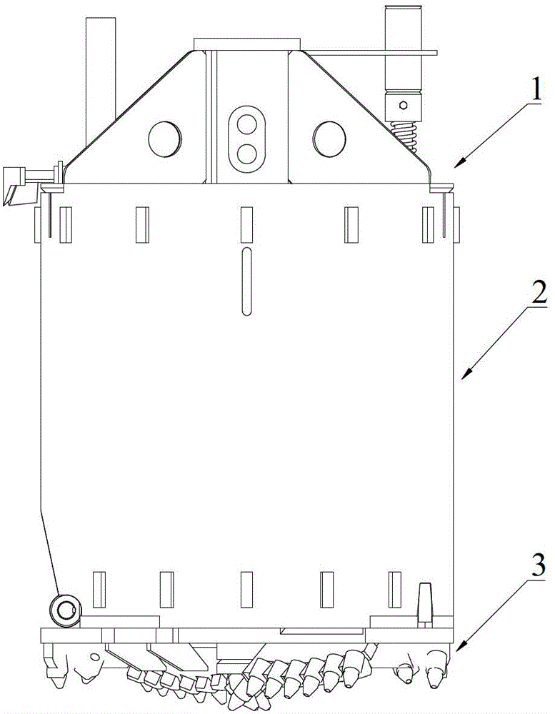
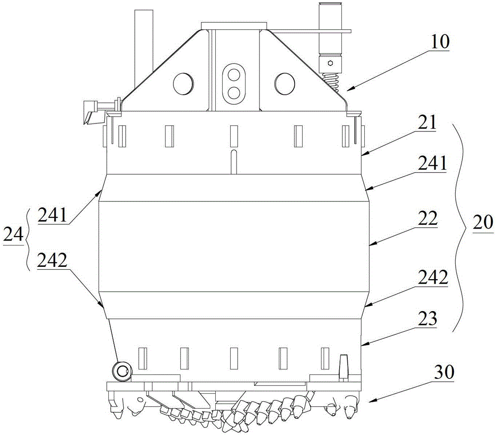
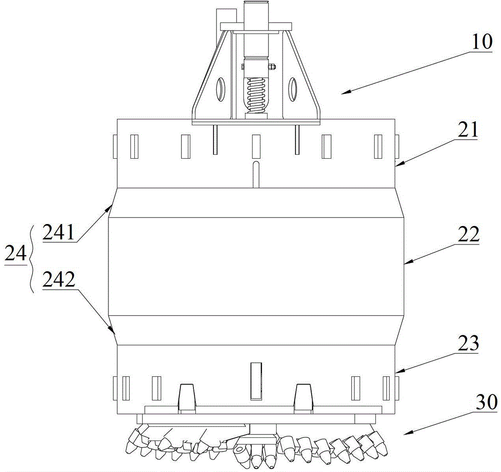
[0032] Such as figure 2 Shown is a schematic structural view of a drilling bucket provided by an embodiment of the present invention, image 3 It is a structural schematic diagram of the other side of the drill bucket, which can be referred to at the same time for easy understanding. The drill bucket includes the upper bottom 10 of the drill bucket, the lower bottom 30 of the drill bucket, and the drill bucket connecting the upper bottom 10 of the drill bucket and the lower bottom 30 of the drill bucket. Cylinder 20, the maximum diameter of the drill bucket cylinder 20 is gr...


PUM


Abstract

The invention discloses a drilling bucket and a rotary drilling rig, wherein the drilling bucket comprises a drilling bucket upper bottom part, a drilling bucket lower bottom part, and a drilling bucket barrel connecting the drilling bucket upper bottom part with the drilling bucket lower bottom part, and the maximum diameter of the drilling bucket barrel is larger than the maximum diameter of the drilling bucket upper bottom part and the maximum diameter of the drilling bucket lower bottom part. The drilling bucket provided by the invention adopts the invention of unequal diameters, the maximum diameter of the drilling bucket barrel is designed to be larger than the maximum diameter of other parts of the drilling bucket, then the drilling bucket barrel can be in tight fit with the hole wall in the drilling process and has certain drilling guide effect, the problem of deflective drilling is effectively solved, the impact on the drilling bucket and the lateral force transmitted upwards to structures like a drilling rod and a mast are reduced, the working stability of a main engine structure of the rotary drilling rig is improved, and meanwhile, the hole wall is fixed. The rotary drilling rig provided by the invention also has the benefits.

Description

technical field [0001] The invention relates to the field of engineering machinery, in particular to a drilling bucket and a rotary drilling machine with the drilling bucket. Background technique [0002] At present, the rotary drilling rig has been widely used in pile foundation construction. During the construction process, the rotary drilling rig transmits torque and pressure to the drill pipe, and the drill pipe transmits torque and pressure to the drilling tool (such as a drill bucket, etc.). The currently used drilling bucket structure is as follows: figure 1 As shown, it mainly includes the following parts: the upper bottom of the drilling bucket 1, mainly including the connecting square, the upper bottom of the drilling bucket, the unlocking guide rod of the drilling bucket, etc.; the drilling bucket cylinder 2 is a cylinder structure with a certain diameter; the drilling bucket The lower bottom 3 mainly includes the bottom of the bucket, picks and the like. The pi...

Claims


Application Information

Patent Timeline
Patent Type & Authority Patents(China)
IPC IPC(8): E21B10/00
Inventor 于兴哲张伟王海博
Owner BEIJING SANY HEAVY MASCH CO LTD
Why Eureka
Try Eureka