AI technical title is built by PatSnap AI team. It summarizes the technical point description of the patent document.
A cycle power and air energy technology, applied in the field of air energy cycle power generators, can solve the problems of emission of harmful gases, use cost, poor generator endurance, and high cost, and achieve the effects of convenient operation, convenient source and small size
Inactive Publication Date: 2015-04-29
SHENZHEN PINCHUAN ENERGY ELECTRIC CO LTD
View PDF4 Cites 0 Cited by
Summary
Abstract
Description
Claims
Application Information
AI Technical Summary
This helps you quickly interpret patents by identifying the three key elements:
Problems solved by technology
Method used
Benefits of technology
Problems solved by technology
In order to solve the technical problems existing in the existing technology, such as the harmful gas emission of the fuel generator, the high cost of use, the poor endurance of the generator, and the high cost
Method used
Image
Click on the blue label to locate the original text in one second.
Reading with bidirectional positioning of images and text.
Examples
Embodiment Construction
[0014] The technical solution of the present invention will be further specifically described below through the embodiments and in conjunction with the accompanying drawings.
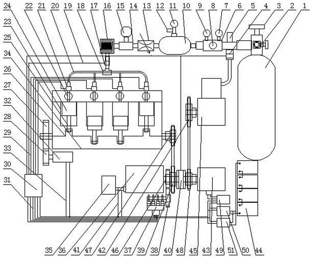
[0015] figure 1 It is a structural schematic diagram of the air energy cycle engine of the present invention. Depend on figure 1 It can be seen that the air energy cycle power generator is mainly composed of gas energy storage device, engine air supply control device, solenoid valve gas control system, power generation and power supply device, air energy engine, engine starting device, DC motor transmission device, air supply cycle control device ; Wherein the gas energy storage device is connected with the engine gas supply control device, the gas energy storage device includes a gas storage tank 1, a gas filling valve interface 2, a gas storage tank switch valve 3, and a gas storage tank safety valve 5; wherein the gas storage tank 1 adopts It is a carbon fiber gas tank, and the air filling valve in...
PUM
Abstract
An air energy cycle power generator comprises an air energy storage device, an engine air supply control device, an electromagnetic valve air control system, a power generation, charging, supply and storage device, a power generation and supply device, an air engine, an engine starting device, a direct current motor transmission device and an air supply cycle control device. The air energy storage device is in communication with the motor air supply control device, and the engine air supply control device comprises a pressure reduction valve assembly (6), a buffering pot (10), a gas flow control valve (13), and a gas heat exchanger (16); a gas outlet of the gas heat exchanger (16) is connected to an air inlet of an air pipe three-way joint (18) by using a gas electromagnetic main valve (17), and a gas outlet of the air pipe three-way joint (18) is separately in communication with four air inflow cavities of the engine body of the air engine (34) by using a branch cylinder gas pipeline (20); the air supply cycle control device comprises an air compressor (45), a compressor electromagnetic clutch (40), and an air pressure control sensor (4); a gas outlet of the air compressor (45) is in communication with a pipeline of the air energy storage device by using the air pressure control sensor (4); the power generation and supply device comprises an alternating current generator (36), an alternating current generator output line (41), and an electrical appliance (35), and a transmission shaft of the alternating current generator (36) is coaxially connected to a transmission chain wheel (39) disposed on the compressor electromagnetic clutch (40); and the compressor electromagnetic clutch (40) is provided with the transmission chain wheel (39), and a driven chain wheel (48), and the driven chain wheel (48) is chained to a compressor transmission chain wheel (42) on the air compressor (45); the transmission chain wheel (39) is chained to an output shaft wheel (47) of the engine body of the air engine; the direct current motor transmission device comprises a direct current motor (43), a rectifying, charging and voltage stabilizing module (50), a direct current motor program controller (49), a rectifying inverter (51), and a battery set (44); a rotating shaft of the direct current motor (43) is connected to a driven chain wheel shaft of the compressor electromagnetic clutch, the direct current motor (43) is connected to the rectifying, charging and voltage stabilizing module (50), and the rectifying inverter (51) by using the direct current motor program controller (49), and the rectifying, charging and voltage stabilizing module (50) is connected to the rectifying inverter (51) and the battery set (44).
Description
technical field [0001] The invention relates to the technical field of new energy machinery, in particular to an air energy cycle power generator. Background technique [0002] With the rapid development of modernization, the application of electric power in all walks of life is more and more extensive, which makes the power more and more tense, and the power generation equipment used is also diversified, especially fuel generators are the most popular and widely used. Indeed, fuel generators give People's life has brought convenience, but after the fuel generator completes its work, the waste gas produced is discharged into the atmosphere, which pollutes the environment and has a negative impact on people's health. Due to the rapid increase of fuel-fired generators and the consumption of fuel oil, petroleum energy is becoming increasingly tense, and the price of petroleum raw materials has soared again and again. Moreover, the large consumption of natural fuel energy is app...
Claims
Application Information
Patent Timeline
Application Date:The date an application was filed.
Publication Date:The date a patent or application was officially published.
First Publication Date:The earliest publication date of a patent with the same application number.
Issue Date:Publication date of the patent grant document.
PCT Entry Date:The Entry date of PCT National Phase.
Estimated Expiry Date:The statutory expiry date of a patent right according to the Patent Law, and it is the longest term of protection that the patent right can achieve without the termination of the patent right due to other reasons(Term extension factor has been taken into account ).
Invalid Date:Actual expiry date is based on effective date or publication date of legal transaction data of invalid patent.

