
A transmission

A transmission device, linear transmission technology, applied in the direction of transmission device, gear transmission device, hoisting device, etc., can solve problems such as torque gap, achieve the effect of eliminating torque gap, reducing wear and avoiding restraint state

Active Publication Date: 2013-10-23
WITTENSTEIN GROUP
View PDF8 Cites 16 Cited by
  • Summary
  • Abstract
  • Description
  • Claims
  • Application Information

AI Technical Summary

Problems solved by technology

[0003] Despite the high torsional rigidity of this transmission, torque gaps occur when the load changes

Method used


Image

  • A transmission
  • A transmission
  • A transmission

Examples


Embodiment Construction

[0048] Exemplary embodiments of the present invention will be described below with reference to the accompanying drawings. The invention is not limited to the exemplary embodiments; rather, the scope of the invention should be determined by the claims. In the description of the embodiments, the same reference numerals are used to refer to the same components in different drawings or in some cases to refer to similar components, and to make the description for different embodiments easier to understand. However, this does not imply that the corresponding parts of the invention are limited to the forms of the described embodiments.

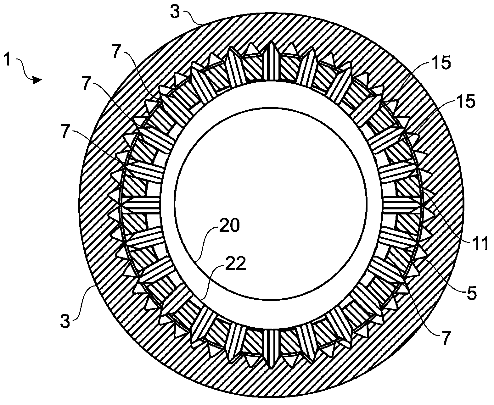
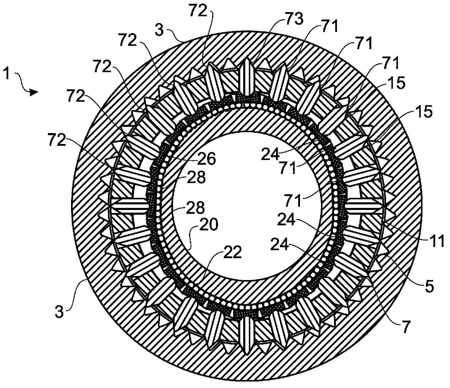
[0049] figure 1 A side view of an exemplary embodiment is schematically depicted. figure 1 A section through a transmission 1 with a ring gear 3 with inner peripheral toothing 5 is shown. The tooth segment 7 meshes with the toothing 5 . For clarity, it is not figure 1 Each tooth segment 7 in is provided with a reference numeral 7. The tooth se...


PUM


Abstract

A transmission, in particular a coaxial transmission or linear transmission, comprising a toothing, a tooth holder in which a plurality of tooth segments are accommodated to engage with the toothing, wherein the tooth segments are borne to be radially shiftable relative to the tooth holder, a drive element having a profiling for radially driving the tooth segments borne in a radially shiftable manner, wherein the transmission has inner initial stress.

Description

technical field [0001] The invention relates to a transmission according to claim 1 and to a method of manufacturing and operating a transmission according to the independent claim. Background technique [0002] Transmissions known from the prior art comprise toothed segments mounted radially displaceable in toothed seats. For driving the tooth segments, profiled drive elements, such as cam discs, can be used. The teeth of the tooth segments mesh with the edge teeth, so that a relative movement between the tooth holder with the tooth segments and the edge teeth is brought about. The relative movement between the toothing and the tooth segment is at least an order of magnitude smaller than the movement of the profiled drive. In this way a high transmission ratio can be achieved; an example of such a transmission is disclosed in DE 10 2007 011 175 A1. [0003] Despite the high torsional rigidity of this transmission, torque gaps can occur when the load changes. However, to...

Claims


Application Information

Patent Timeline
Patent Type & Authority Applications(China)
IPC IPC(8): F16H1/32F16H55/02
CPCF16H55/08F16H25/02F16H25/06Y10T29/49464Y10T74/1987F16H25/2009
Inventor 迈克尔·施密特汉克·施赖伯弗兰克·米歇尔托马斯·拜尔
Owner WITTENSTEIN GROUP
Learn More