

Lamp body mounting pillar structure
A technology for installing columns and lamp bodies, which is applied in lighting devices, gas/waterproof devices, and components of lighting devices, etc., can solve problems such as affecting the layout of parts, easy breakage of the mounting columns, and inability to adjust the dimming structure of the combined lamp. , to reduce shrinkage and improve quality
- Summary
- Abstract
- Description
- Claims
- Application Information
AI Technical Summary
Problems solved by technology
Method used
Image

Examples
Embodiment Construction
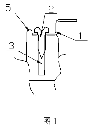
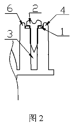
[0008] Depend on figure 1 , figure 2 As we know, the structure of the lamp body mounting column includes self-tapping screws 1, sealing gasket 2, lamp body 3, anti-shrinkage bezel and mounting post 4, the anti-shrinking bezel is composed of slider core pulling 5 and decorative frame 6, and mounting post 4 The middle of the lamp body is solid, and the self-tapping screw 1 and the sealing gasket 2 are used to set it in the lamp body 3. The lamp body 3 and the decorative frame 6 are connected by a mounting column 4, and a mold slide is provided between the mounting column 4 and the decorative frame 6. Block core pulling 5. The thickness of the slider core-pulling 5 of the mold is greater than the thickness of the mounting column 4, and the range is ≥3.5mm.
PUM
 Abstract
Description
Claims
Application Information