

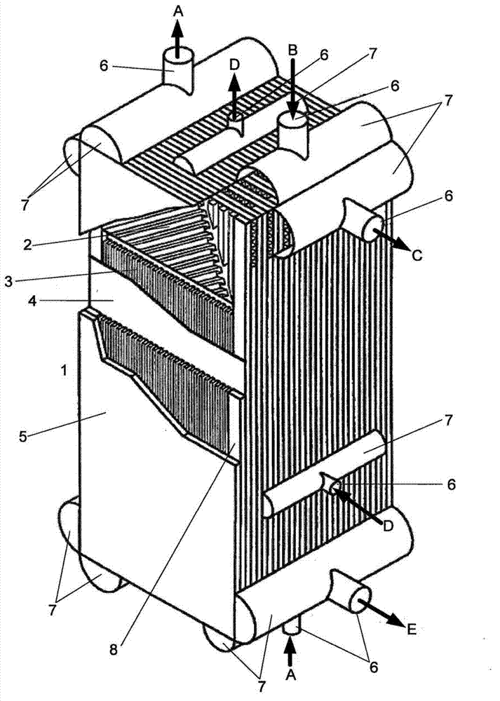
Plate heat exchanger with several modules connected by sheet-metal strips
A technology of plate heat exchanger and heat exchange medium, which is applied in the direction of fixed heat exchanger, indirect heat exchanger, heat exchange equipment, etc., to achieve the effect of improving thermal contact, improving mechanical connection and thermal connection
- Summary
- Abstract
- Description
- Claims
- Application Information
AI Technical Summary
Problems solved by technology
Method used
Image

Examples
Embodiment Construction
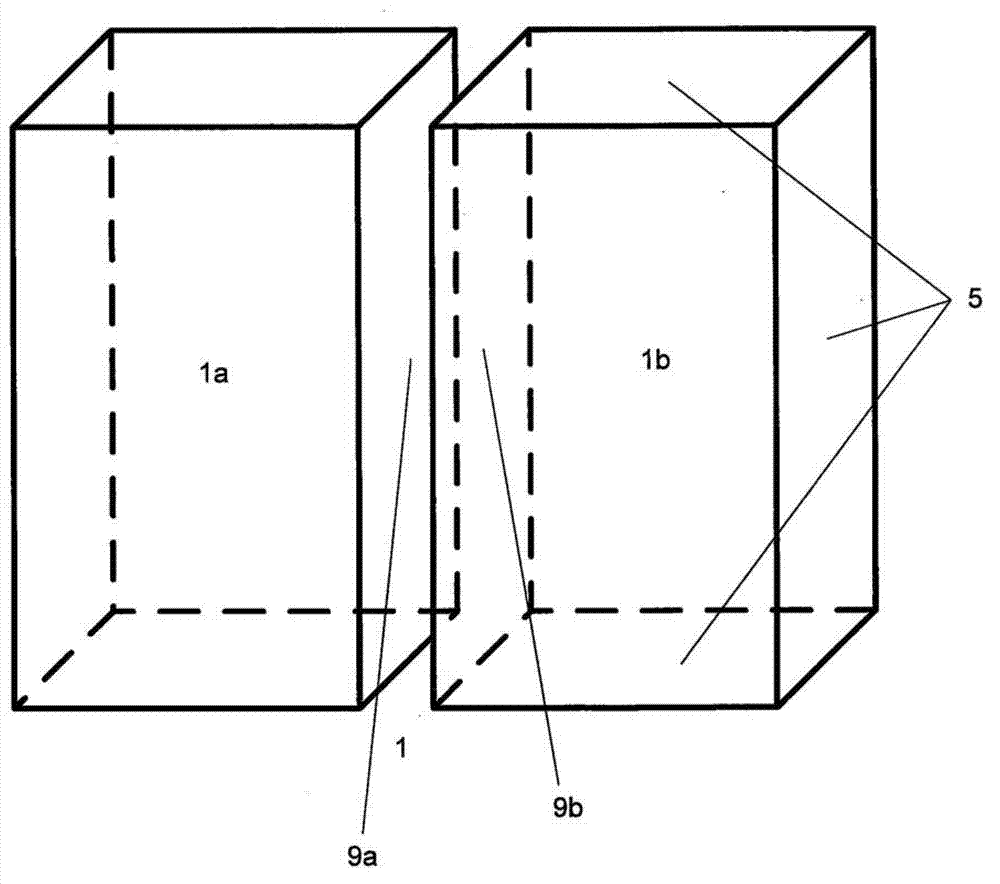
[0034] figure 2 The solution of a plate heat exchanger 1 according to the invention shown in , comprises two modules 1a and 1b. The two modules 1 a and 1 b are rectangular parallelepiped-shaped and are each closed to the outside by a cover 5 . The two modules 1a and 1b are arranged such that cover sheets 9a and 9b correspondingly of the same size are directly adjacent. The two cover sheets 9 a and 9 b form the contact surface between the two modules 1 a and 1 b of the plate heat exchanger 1 . The two contact surfaces 9a and 9b are connected to one another by a suitable adhesive.
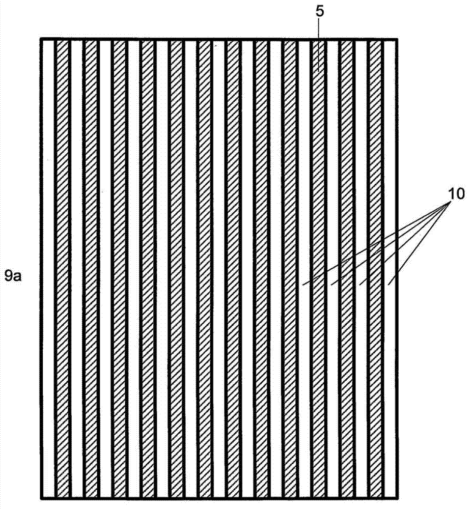
[0035] exist image 3 Details are shown in . exist image 3 The contact surface 9a is shown in . The cover sheet 5 (shown shaded) is provided with adhesive. A plurality of sheet metal strips 10 are connected to the contact surface 9a by means of an adhesive. The sheet metal strip 10 has a length corresponding to the edge length of the cover sheet 9a. The sheet metal strips 10 are arranged r...
PUM
 Abstract
Description
Claims
Application Information