Oil charging device oil permeating point positioning detector and using method thereof

An oil-filled equipment and point positioning technology, which can solve the problems of time-consuming, inaccurate, and poor versatility, and achieve Simple and convenient operation, accurate positioning effect

Active Publication Date: 2013-10-23
STATE GRID CORP OF CHINA +3
View PDF8 Cites 6 Cited by
  • Summary
  • Abstract
  • Description
  • Claims
  • Application Information

AI Technical Summary

Problems solved by technology

[0004] There are mainly five original methods for finding oil seepage points: ①Eye observation method: Generally, where the wettest point is the oil seepage point, this method has a high misjudgment rate and is inaccurate
②Powdering method: apply chalk near the oil seepage point, and observe where it gets wet first to determine where the oil seepage point is. This method cannot find live equipment
③Water flushing method: It is suitable for finding the leakage point of the cooler pipe of the radiator of the strong oil circulation transformer; it is not versatile and is not suitable for searching for live equipment
④Touch test method: when checking, use hands or tools to touch from top to bottom, and you can find the leak point; maintenance is inconvenient and time-consuming, and it is also not suitable for searching live equipment
This invention is suitable for severe leakage and oil dripping. When the oil leakage point is small, it is not suitable for the leakage part without oil drop, which is easy to cause omission. In addition, the method is not accurate for oil leakage point search and needs assistance Other methods are used to further determine the oil seepage point

Method used


Image

  • Oil charging device oil permeating point positioning detector and using method thereof

Examples


Embodiment Construction

[0025] The present invention will be further described in detail below in conjunction with the accompanying drawings and specific embodiments.

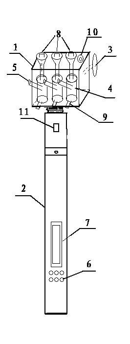
[0026] Such as figure 1 As shown, an oil-filled equipment oil seepage point location detector includes an insulating rod body 2 and an insulating box body 1 placed on the top of the insulating rod body 2; a camera 10 and a detachably connected motorized The insulating brush head 3 and the insulating box body 1 are provided with three automatic sprayers 4, which are respectively used to contain the penetrating agent, the white developer and the cleaning agent. The nozzle 5 of each automatic sprayer 4 passes through the side plate of the insulating box body 1 away from the electric insulating brush head 3; the insulating rod body 2 has a built-in motor 11, and the lower end of the insulating rod body 2 is provided with different gears for controlling the electric insulating brush The rotation or reciprocating movement of the head 3, an...


PUM


Abstract

The invention discloses an oil charging device oil permeating point positioning detector and a using method thereof. The oil charging device oil permeating point positioning detector comprises an insulating rod body and an insulating box body arranged at the top end of the insulating rod body. An electric insulating brush head and a camera are connected to a side plate of the insulating box body, and a plurality of automatic sprayers are arranged inside the insulating box body. A motor is arranged inside the insulating rod body, and switch buttons with different gears are arranged at the lower end of the insulating rod body. The using method comprises the steps of preparing mist spray solvent, rinsing greasing, spraying penetrant, washing the penetrant, spraying white photographic developer, photographing and positioning oil permeating points. By means of the structure and the method, an electrically charged device does not need to be turned off, a user only needs to stand on the ground and turns on the switch buttons of the corresponding gears, then, cleaning agents are automatically sprayed, the electric insulating brush head cleans and scrubs, the penetrant and the white photographic developer are automatically sprayed and photographing is carried out on the oil permeating positions, an operator observes blackened and darkened points of the white photographic developer from a video or an image, and the points are the oil permeating points. Operation is easy and convenient, and the oil permeating points are positioned accurately.

Description

[0001] technical field [0002] The invention relates to a detection device used in a power system and a use method thereof, in particular to an oil-filled equipment oil seepage point location detector and a use method thereof. Background technique [0003] Oil-filled equipment such as transformers and transformers is the main equipment in the substation. After a period of operation, due to welding quality problems, poor sealing, and inaccurate oil leakage points, the oil-filled equipment will leak oil. The oil leakage of these equipment will affect the safe operation of electrical equipment, thus arousing great attention of the electric power industry. Because the oil seepage point is very small, how to accurately locate the oil seepage point is a difficult problem. [0004] There are mainly five original methods for finding oil seepage points: ①Eye observation method: Generally, where the wettest place is the oil seepage point, this method has a high misjudgment rate and ...

Claims


Application Information

Patent Timeline
IPC IPC(8): G01M3/12
Inventor 苑超山魏政葛亮陈科邓佳宾
Owner STATE GRID CORP OF CHINA
Why Eureka
Try Eureka