Holographic representation device, holographic representation method, holographic realization equipment and holographic realization method

A reproduction device, holographic technology, applied in the fields of holographic realization, holographic realization equipment, and holographic reproduction device, which can solve the problem of unique viewing angle

Active Publication Date: 2013-10-23
BOE TECH GRP CO LTD +1
View PDF5 Cites 22 Cited by
  • Summary
  • Abstract
  • Description
  • Claims
  • Application Information

AI Technical Summary

Problems solved by technology

[0006] The purpose of the present invention is to provide a method in which the present invention relates to the field of display technology, and in particular to a holographic reproduction device, a holographic reproduction method, a holographic realization device a

Method used


Image

  • Holographic representation device, holographic representation method, holographic realization equipment and holographic realization method
  • Holographic representation device, holographic representation method, holographic realization equipment and holographic realization method
  • Holographic representation device, holographic representation method, holographic realization equipment and holographic realization method

Examples


Embodiment 1

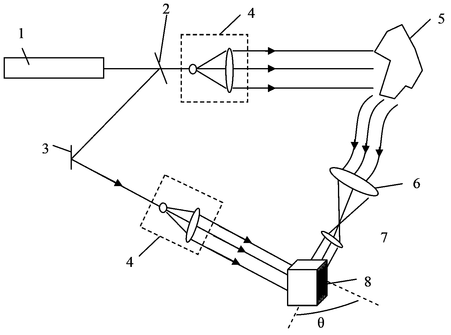
[0053] This embodiment provides a holographic recording device and a holographic recording method, which are used to obtain the photorefractive crystals recorded with holographic images required in the second implementation example below; the holographic recording device provided by this embodiment mainly includes :

[0054] The light source provides the reference light incident on the photorefractive crystal and the object light incident on the subject, the reference light and the object light are coherent light;

[0055] The photorefractive crystal receives the reference light and the object light reflected by the object to form a holographic image;

[0056] The first rotating mechanism is used to rotate the photorefractive crystal by a preset angle after each recording of a holographic image by the photorefractive crystal.

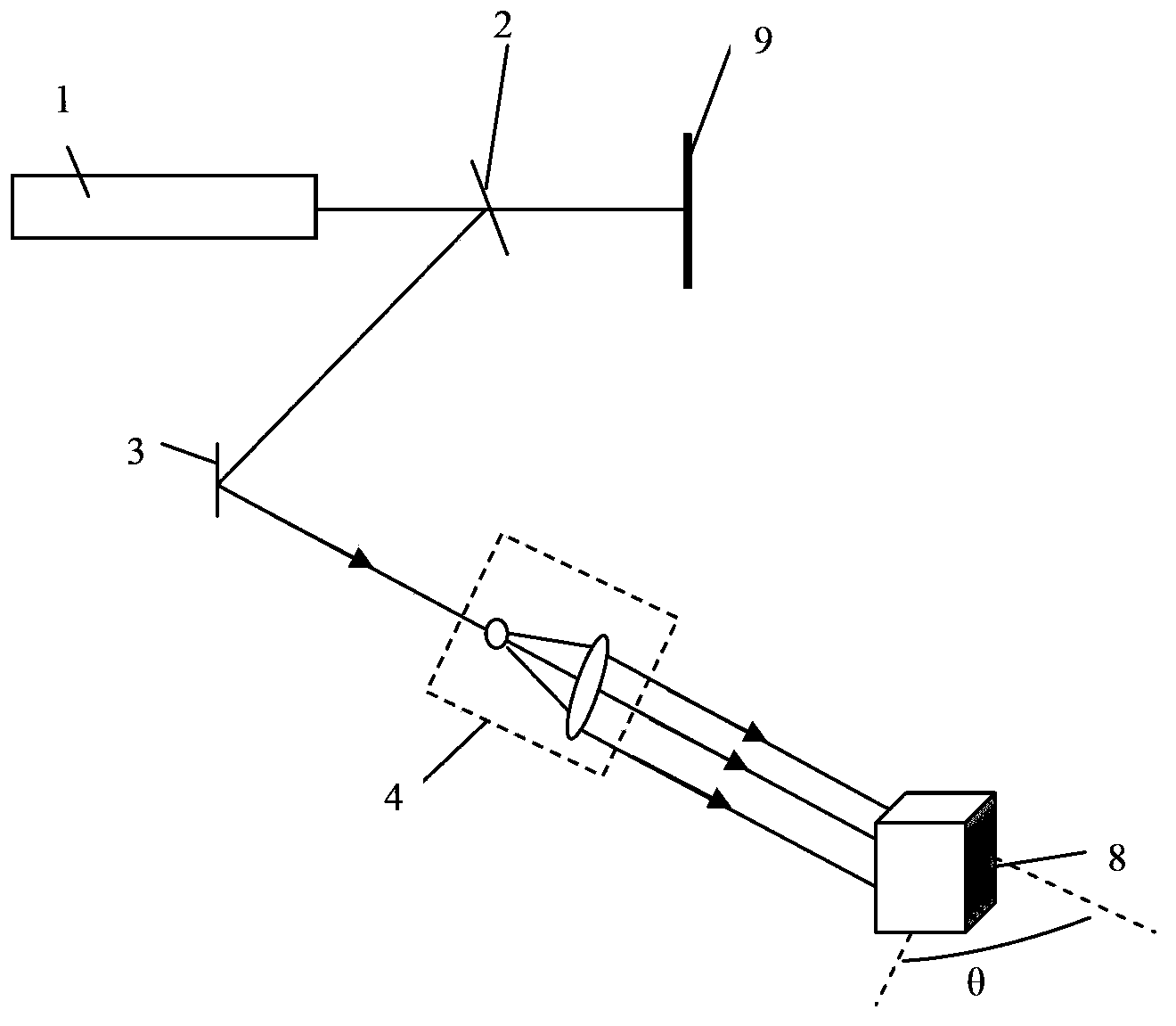
[0057] The holographic recording method provided in this embodiment mainly includes:

[0058] The reference light and the object light reflected by t...

Embodiment 2

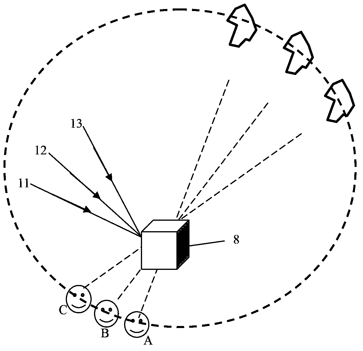
[0069] This embodiment provides a holographic reproducing device and a holographic reproducing method for reproducing the holographic image recorded by the holographic recording device and the holographic recording method provided in the first embodiment. Of course, the holographic reproducing device and the holographic reproducing method in this embodiment The reproduction method can also be used to reproduce a holographic image recorded by a holographic recording device and a holographic recording method other than the first embodiment. The holographic reproduction device in this embodiment mainly includes:

[0070] Photorefractive crystals, which record holographic images at multiple different angles;

[0071] The light source provides multiple reproduced lights incident on the photorefractive crystal from different angles; the frequency and optical path of the reproduced light are the same as those of the reference light when forming the holographic image.

[0072] The ho...


PUM


Abstract

The invention relates to the technical field of displaying, in particular to a holographic representation device, a holographic representation method, holographic realization equipment and a holographic realization method. The holographic representation device comprises photorefraction crystals and a light source, wherein the photorefraction crystals respectively record holographic images at multiple different angles, the light source provides lots of representation light incident on the photorefraction crystals from the different angles, and the representation light is the same as reference light in frequency and optical distance when the holographic images are formed. According to the holographic representation device, the representation lights incident on the photorefraction crystals from the different angles are utilized to be irradiated to the photorefraction crystals. Because the holographic images are recorded by the photorefraction crystals at the different angles, each holographic image can be showed at different angles in a non-interfering mode, observers located on multiple positions can observe the holographic images recorded in the photorefraction crystals, and the problem that an observation angle is single in the holographic representation process is solved.

Description

technical field [0001] The present invention relates to the field of display technology, in particular to a holographic reproduction device, a holographic reproduction method, a holographic realization device and a holographic realization method. Background technique [0002] In linear optical materials, such as lenses, prisms, etc., light beams only pass through the optical material without changing certain properties of the optical material itself. The photorefractive effect is the abbreviation of the effect of photoinduced refractive index change. It does not refer to all light-induced refractive index changes, but specifically refers to the formation of a charge field by the photoconductive effect of optical materials under light radiation, and then caused by the photoelectric effect. The effect of the variation of the refractive index with the spatial distribution of light intensity. Since the optical properties of photorefractive crystals can be changed by light passi...

Claims


Application Information

Patent Timeline
IPC IPC(8): G03H1/22G03H1/12
CPCG03H1/2286G03H1/28G03H2001/0268G03H2001/2239G03H2222/34G03H2222/46G03H2260/54G03H1/265G03H1/02G03H1/0465G03H2001/2223G03H2222/54G03H2001/0212G03H2001/0216G03H2222/12
Inventor 郑箫逸王俊伟林鸿涛
Owner BOE TECH GRP CO LTD
Why Eureka
Try Eureka