Flicker regulating system

A technology for adjusting systems and adjusting instructions, applied in instruments, static indicators, etc., can solve problems such as cumbersome maintenance and many structural components, and achieve the effects of fewer components, low hardware cost, and simple structure

Active Publication Date: 2013-10-23
HISENSE VISUAL TECH CO LTD
View PDF5 Cites 17 Cited by
  • Summary
  • Abstract
  • Description
  • Claims
  • Application Information

AI Technical Summary

Problems solved by technology

[0005] The Flicker probe includes structures such as a lens, a light shield, an adjustable pointing ring, and a photoelectric conversion circuit structure. more cumbersome

Method used


Image

  • Flicker regulating system
  • Flicker regulating system
  • Flicker regulating system

Examples


Embodiment Construction

[0034] The Flicker adjustment system of the present invention will be further described below in conjunction with the accompanying drawings and embodiments.

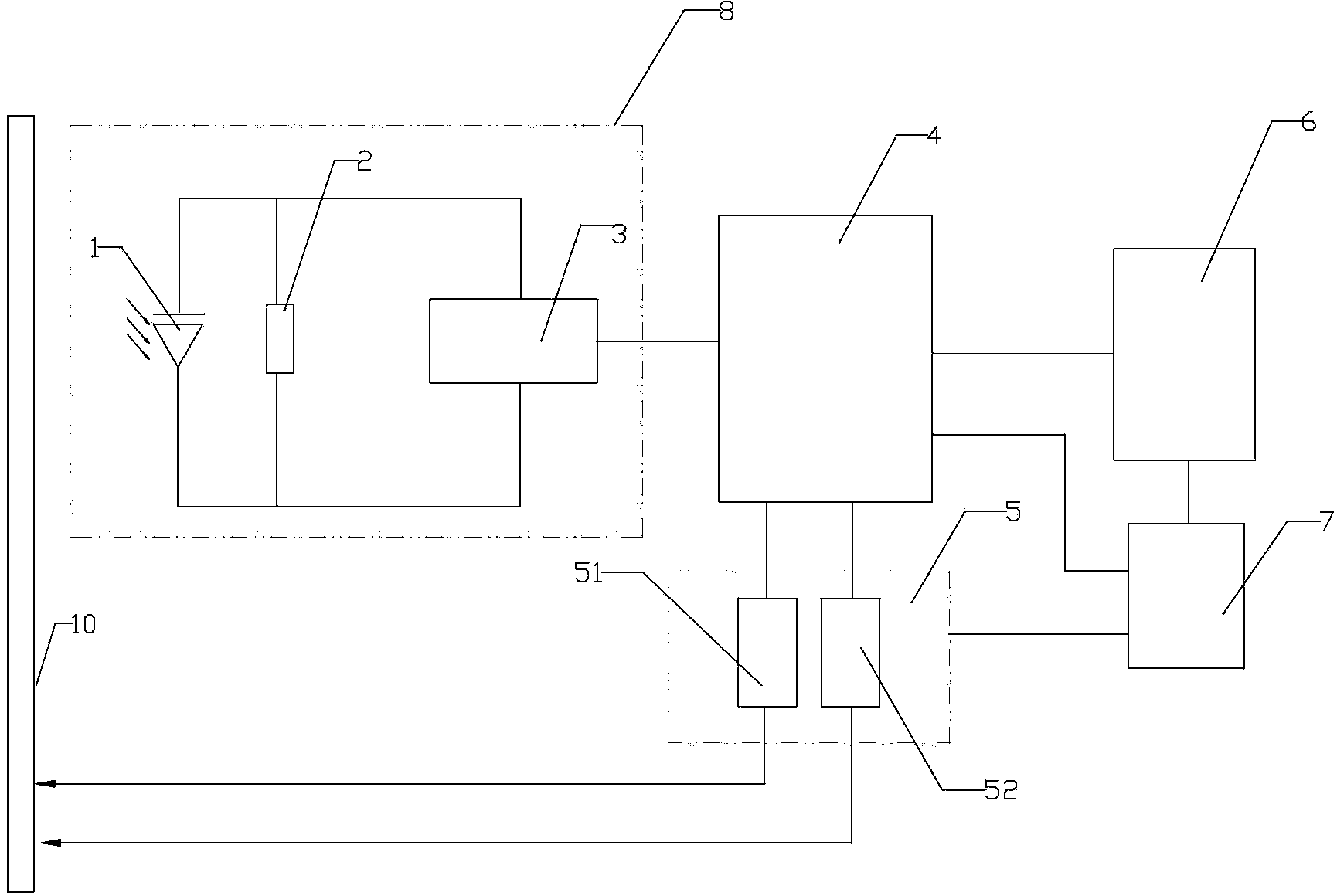
[0035] The flicker in the LCD screen is related to the Vcom voltage value in the Vcom register in the T-con chip—the timing control chip. If the Vcom voltage is too large or too small, it will cause the LCD screen to flicker too much (ie Flicker The value is too large) so that the problem of excessive flickering of the LCD screen can be reduced by adjusting the Vcom voltage.

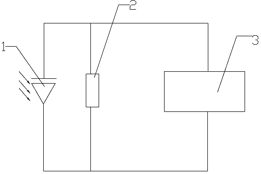
[0036] In the Flicker adjustment system of the present invention, according to the above problems, the test unit directly adopts a photoelectric converter and a signal processing unit, and the photoelectric converter is used to convert the optical signal output by the screen to be tested into an electrical signal, and then through the signal processing The processing of the unit realizes signal conversion, amplification and other processing, and ou...


PUM


Abstract

The invention discloses a flicker regulating system which resolves the problems that an existing structure is complex and hardware cost is high. The flicker regulating system comprises a test unit which comprises a photoelectric converter and a signal processing unit connected with the photoelectric converter, and the test unit is used for measuring and outputting test signals relevant to flicker of a screen to be tested. A master controller comprises a receiving module, a regulating command generating module and a regulating command output module, wherein the receiving module is used for receiving the test signals, the regulating command generating module is used for analyzing and processing the test signals according to preset programs and generating regulating commands, and the regulating command output module is used for outputting the regulating commands into the screen to be tested to control regulation of Vcom voltage in the screen to be tested. The flicker regulating system has the advantages of being simple in structure, low in cost, easy and convenient to realize, and wide in application range.

Description

technical field [0001] The invention relates to the display field, in particular to a Flicker adjustment system. Background technique [0002] At present, in the production process of the liquid crystal screen, flicker (flicker degree) needs to be adjusted, so that the flicker of the picture falls within a preset range value to improve the viewing experience. There are currently two Flicker moderation tools: [0003] The first type: manual adjustment tool - special Flicker adjustment tool head, manual adjustment and human eyes to observe whether the adjustment is completed, using Flicker adjustment tool head, the adjustment efficiency is low, and the adjustment accuracy is poor. [0004] The second type: automatic adjustment tool - Flicker automatic adjustment system, including Flicker probe controller, computer and interface board and other components. The Flicker probe is used to collect flicker signals from the screen to be tested, and the main controller analyzes and p...

Claims


Application Information

Patent Timeline
Patent Type & Authority Applications(China)
IPC IPC(8): G09G3/00
Inventor 张啸栾复磊于洋
Owner HISENSE VISUAL TECH CO LTD
Why Eureka
Try Eureka