The fuel cell

A technology for fuel cells and electrolyte membranes, which is applied in the fields of fuel cells, fuel cell additives, and fuel cell components, and can solve problems such as inability to circulate fluids.

Active Publication Date: 2015-10-14
HONDA MOTOR CO LTD
View PDF3 Cites 0 Cited by
  • Summary
  • Abstract
  • Description
  • Claims
  • Application Information

AI Technical Summary

Problems solved by technology

Therefore, there is a problem that if the fluid flowing on one surface side of the metal separator cannot be smoothly circulated, the fluid flowing on the other surface side cannot be smoothly circulated.

Method used


Image

  • The fuel cell
  • The fuel cell
  • The fuel cell

Examples


Embodiment Construction

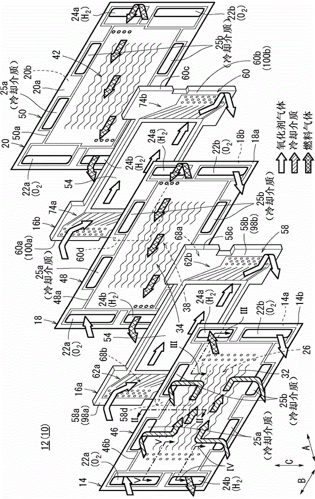
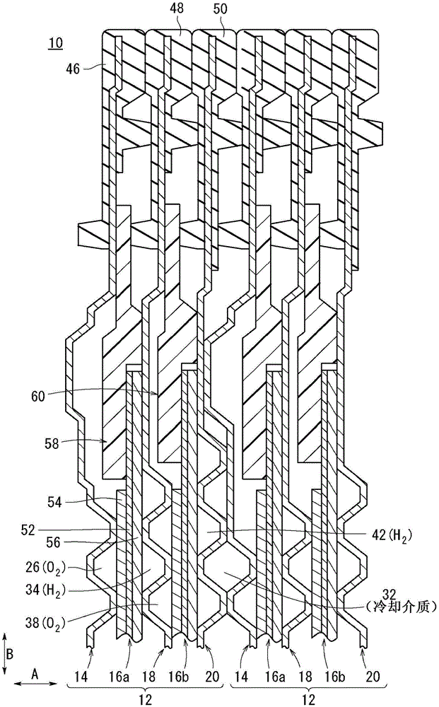
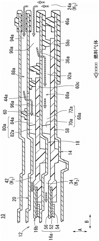
[0070] Such as Figure 1 to Figure 5 As shown, the fuel cell 10 according to the first embodiment of the present invention includes power generating units 12 , and a plurality of power generating units 12 are stacked on each other along the horizontal direction (arrow A direction) or the vertical direction (arrow C direction). The power generation unit 12 is provided with a first metal separator 14 , a first electrolyte membrane-electrode structure 16 a , a second metal separator 18 , a second electrolyte membrane-electrode structure 16 b and a third metal separator 20 .

[0071] The first metal separator 14, the second metal separator 18, and the third metal separator 20 are made of, for example, steel plates, stainless steel plates, aluminum plates, plated steel plates, or steel plates with anti-corrosion surface treatments on their metal surfaces. Shaped sheet metal. The first metal separator 14 , the second metal separator 18 , and the third metal separator 20 have a rect...


PUM


Abstract

A fuel cell includes a membrane electrode assembly, a first separator, and a second separator. The membrane electrode assembly includes a first electrode, a second electrode, a resin frame member, and an electrolyte membrane. The resin frame member includes a first surface, a second surface, a first buffer portion, and a second buffer portion. The first buffer portion is provided on the first surface of the resin frame member. The second buffer portion is provided on the second surface of the resin frame member. The second buffer portion is independent from the first buffer portion.

Description

technical field [0001] The present invention relates to a fuel cell which has a separator and an electrolyte membrane-electrode structure in which a pair of electrodes are provided on both sides of an electrolyte membrane, and a reactor for supplying a reaction gas along the electrode surface is provided on the separator. a gas flow path and a reaction gas communication hole through which the reaction gas flows in the lamination direction of the electrolyte membrane-electrode structure and the separator; on the other hand, the electrolyte membrane-electrode structure is provided With resin frame member. Background technique [0002] For example, a solid polymer fuel cell includes a power generation cell (unit cell) in which an electrolyte membrane-electrode assembly (MEA) is sandwiched between separators on a solid polymer ion exchange An anode electrode and a cathode electrode are respectively arranged on both sides of the polymer electrolyte membrane. In fuel cells, seve...

Claims


Application Information

Patent Timeline
Patent Type & Authority Patents(China)
IPC IPC(8): H01M8/04H01M8/02
CPCH01M8/0258H01M8/0267H01M8/1004Y02E60/50Y02E60/521H01M8/0273H01M2008/1095H01M8/2483H01M8/241H01M8/2457H01M8/026
Inventor 石田坚太郎杉田成利后藤修平
Owner HONDA MOTOR CO LTD
Why Eureka
Try Eureka